Advertisement
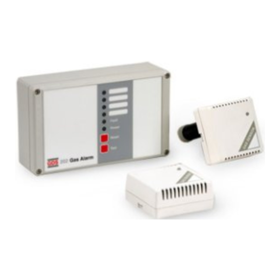
GDS 202 GAS ALARM
TECHNICAL
Zone Signal Selectors
Zone Signal Selectors
Transformer
Remote Reset
Transformer
Remote Reset
F2
F1
R
T
F2
R
F1
T
1 2 3
4 5 6 7 8 9 10 11 12 13 14 15
-
+
E
L
N
1 2 3 4
1 2 3 4
1 2 3 4
1 2 3
4 5 6 7 8 9 10 11 12 13 14 15
-
Mains
ZONE-SIG
+
in
SENSOR
SENSOR
E
L
N
1 2 3 4
1 2 3 4
1 2 3 4
CONTROL UNIT
Mains
ZONE-SIG
in
SENSOR
SENSOR
Power Supply
230/115vAC or 24vDC ± 15%
The two voltages may be used at the same time (standby battery)
24vDC-200mA max. - auxiliary equipment
Frequency
50/60 Hz
Power Output
Consumption
3 watts
Detector Head
Standard l to 10 (Auxiliary power supply - 1 to 20) Toxic and/or
flammable sensors
Indicators
Power - (Green LED)
Pre alarm - (Flashing red alarm LED and intermittent sounder)
non latch
Test Switch
Sensitivity adjustment
Full alarm - (Constant red alarm LED and sounder) - latching
(optional non-latch)
Test Switch
Sensitivity adjustment
Fault - (Amber LED and sounder) Fault monitoring -
sensor/sensor cable/control unit - non latching
Sensor Cable
Alarm LED
3 core I mm
2
Cable length - 200m max
Alarm LED
Alarm Relays
Sounder
Pre alarm S.P.C.O. (R1)
Full alarm D.P.C.O (R2)
Sounder
Fault alarm S.P.C.O (R3)
Spare
Remove EOL
Relays are de energised in non-alarm state (option-energised)
-
s
+
- s
link from all
Spare
All contacts rated - 5A @ 230v AC (none inductive loads only)
Remove EOL
but last sensors
OUT
Relay Inhibit:
Front panel access
-
s
+
- s
link from all
Remote Reset
Option
but last sensors
OUT
Protection:
IP65
Weight :
920 gms
Dimensions:
L 200mm x H l20mm x D 58mm
SENSOR
Power Supply
12 to 30v DC
Consumption
1.2 W
Flam
R
Indicators
Power (Green LED)
Flam
Gas Alarm (Green LED to red and sounder) - non latching
R
F200
Flammable Gas
-
s
+
- s +
-
s
+
- s +
Alarm Threshold F200 1% CH4 Adjustable - Red ident.
-
T200
-
s
+
- s +
Carbon Monoxide
-
s
+
- s +
FSig
+
Alarm Threshold T200 50ppm Adjustable - Yellow ident.
-
FSig
R200
Refrigerant Gas
+
Alarm Threshold R200 Adjustable - Green ident.
Ambient Temperature Operation: -5 to 45°C Storage: +10 to +60°C
Protection
IP42
GDS 202
GDS 202
INSTALLATION
Warning: No termination or wire connections should be made while the system is
powered up.
Control Unit: The control unit should be mounted in a position which is accessible
F
3 wire
and in the field of vision and not directly above cooking appliances or sinks.
3 wire
Mains supply should be from a 1A fused unswitched outlet to BS5733. Internal
3 wire
F
wires should be routed away from electronic components.
3 wire
T
T
T
3 wire
Sensors: The positioning of sensors depends upon the type of gas to be
3 wire
T
T
T
3 wire
monitored and its density with respect to air. Heavy gases (LPG, Propane, Butane,
3 wire
Refrigerant Gases) - Locate at 15 to 20 cm from the floor. Lighter Gases (Methane,
Natural Gas, Town Gas) - Locate at 5 to 10cm from the ceiling. Carbon Monoxide -
Locate at 1.5 to 2 metres from the floor. All equipment should be mounted away
from direct heat, Sensors should not be located outside or where temperatures are
outside the operational specification.
For further information see website - www.gds-technologies.co.uk
SETTING UP
Having terminated all cables the following link adjustments should be made:
A.
Controller - signal in selection
Remove the link from the selected sensor sig input Z1, Z2, Z3, Z4
B.
Sensor end of line link
End of line link (EOL) should be removed from all but the end sensor board,
(each sensor line used).
This document is non contractual and the equipment specification and detail may be modified at any time without prior notice.
Tel +44 (0)113 286 0166 Fax +44 (0)113 287 8178 Email sales@gds-technologies.co.uk www.gds-technologies.co.uk
Remote
Sounder
Remote
Remote
Inhibit
Sounder
Remote
Auto
Sounder
Inhibit
Reset
Auto
Mute
Sounder
Reset
Mute
Alarm
Relays
Alarm
Relays
Field
Terminals
Field
Terminals
16 17 18 19 20 21 22 23 24 25 26 27 28 29 30
+
-
E
NC C NO
NC C NO NC C NO NC C NO
16 17 18 19 20 21 22 23 24 25 26 27 28 29 30
24
R1
RL2
volts
+
-
E
PRE-AL
FULL-ALARM
FAULT
NC C NO
NC C NO NC C NO NC C NO
24
R1
RL2
volts
PRE-AL
FULL-ALARM
FAULT
Sensor
Sensor
+
Terminals
IN
Ambient Temp
+
Terminals
Operation:
-5 to +45°C
IN
Storage:
+10 to +60°C
Flam
Toxic
Flam
Toxic
-
s
+
- s +
-
s
+
- s +
-
s
+
- s +
-
s
+
- s +
F
F
F
F
T
T
T
T
T
T
GDS Technologies Ltd
Fusion Point, Ash Lane, Garforth, Leeds UK LS25 2GA
Test Switch
1 2 3
4 5 6 7 8 9 10 11 12 13 14 15
+
E
L
N
1 2 3 4
Mains
in
SENSOR
Alarm LED
Remove EOL
link from all
but last sensors
OPERATION
On power up, the green power indicator will flash for 3 minutes, indicating that the
Test Switch
sensors are stabilising, during this timed period all alarm functions are held in the off
condition.
After the stabilisation period, any sensor detecting gas will provide a local visual (red
Flam
Alarm LED
LED) and audible alarm, at the same time transmitting a signal to the control unit
RL3
where a pre alarm is indicated by an intermittent audible alarm and the red alarm
RL3
LED flashing with the pre alarm relay changing state. Should the gas surrounding the
-
s
+
sensor clear within 45 seconds the system will return to the normal operating
-
condition. However, if the gas remains for longer than 45 seconds, full alarm
FSig
+
Remove EOL
condition will occur and be indicated by the red alarm LED and sounder going
link from all
constant as well as the full alarm relay activating.
but last sensors
The audible alarm may be silenced at any time but full alarm indication will be
latched until the gas has cleared after which the system may be reset by pressing
the reset pad.
Flam
F
-
s
+
T
T
-
FSig
+
F
T
T
TESTING
The system may be electrically tested by pressing the test pad located on the
control unit for 15 seconds, after which the pre-alarm state will be initiated (with the
exception of relay. By maintaining pressure on the test pad for a further 15
seconds a full alarm condition will result (including the operation of both alarm
relays).
Each sensor has an individual test switch which when pressed simulates gas
present and turns the green LED to red and switches the sounder on.
To ensure that the system responds correctly to the presence of gas, each sensor
should be exposed to test gas. It is advisable to carry out this test at least every
six months.
During test periods alarm relays may be inhibited by pressing the reset pad for 15
seconds after which the fault indicator will illuminate and maintain all relays in the
T
normal non-alarm state, pressing the reset pad again for 15 seconds will remove
the inhibit.
T
Optional normally energised relays
Relays may be individually set to be normally energised or de-energised. Press
and hold the test button, within 2 seconds press and hold the reset button, after 15
seconds all alarm L.E.D's will turn on, release both buttons immediately.
Relay Set-up status
Red zone alarm L.E.D. FLASHING - Normally de-energised
Red zone alarm L.E.D. ON CONSTANT - Normally energised
Z1 indicator - pre-alarm relay
Z2 indicator - Full alarm relay
Z3 indicator - Faulty alarm relay
The zone 1 L.E.D. will now be ON. Press the test button for selection of either
energised or de-energised - see relay status above.
When selection is made press the reset button, Z2 full alarm relay selection may
now be carried out repeat for Z3. Having pressed the reset button on completion of
the fault alarm relay setting the unit will be in normal operating mode.
Sensitivity adjustment
16 17 18 19 20 21 22 23 24 25 26 27 28 29 30
-
+
-
1 2 3 4
1 2 3 4
E
Sensor
NC C NO
24
ZONE-SIG
volts
SENSOR
PRE-AL
Sounder
Spare
-
s
+
- s
+
OUT
IN
Sensitivity adjustment
Sensor
R
Flam
Sounder
- s +
-
s
+
- s +
-
s
+
Spare
-
s
+
- s
+
Terminals
OUT
IN
GDS 202
R
Flam
3 wire
F
F
3 wire
- s +
-
s
+
- s +
-
s
+
- s +
T
T
3 wire
3 wire
GDS 202
3 wire
F
F
3 wire
T
T
3 wire
3 wire
Terminals
ref C486
NC C NO NC C NO NC C NO
R1
RL2
RL3
FULL-ALARM
FAULT
Terminals
Toxic
- s +
-
s
+
- s +
Toxic
-
s
+
- s +
T
T
T
T
T
T
Advertisement
Table of Contents

Subscribe to Our Youtube Channel
Related Manuals for GDS 202


Summary of Contents for GDS 202
- Page 1 This document is non contractual and the equipment specification and detail may be modified at any time without prior notice. GDS Technologies Ltd Fusion Point, Ash Lane, Garforth, Leeds UK LS25 2GA Tel +44 (0)113 286 0166 Fax +44 (0)113 287 8178 Email sales@gds-technologies.co.uk www.gds-technologies.co.uk...
- Page 2 B x4 - 3.5mm, mount using No.8 50mm self tapping screws W/O :- Date :- Type Range Alarm Flammable Toxic Refrigerant 43mm 15mm SIDE VIEW GDS Technologies Ltd Fusion Point, Ash Lane, Garforth, Leeds UK LS25 2GA Tel +44 (0)113 286 0166 Fax +44 (0)113 287 8178 Email sales@gds-technologies.co.uk www.gds-technologies.co.uk...
Need help?
Do you have a question about the 202 and is the answer not in the manual?
Questions and answers