Table of Contents
Advertisement
Quick Links
Advertisement
Table of Contents

Related Manuals for Raider Outboards 55


Summary of Contents for Raider Outboards 55
- Page 1 RAIDER 55 Operator’s Manual...
- Page 2 This page intentionally left blank...
- Page 3 SOF that routinely operate within the often unforgiving, highly demanding, dynamic maritime environment. • Raider Outboards, Inc. is a-US owned and operated company based in Central Florida near Kennedy Space Center, located in the Space Port Commerce Park. We design and produce multi-fuel, submersible, lightweight outboard engines, and associated parts.
- Page 4 • Easy to maintain and troubleshoot. ISSION Raider Outboards will provide and deliver the most reliable premium products, hands on training, and highest quality to the customer and serve as the premier outboard engine company to the U.S. Military; while honoring those who protect, defend, and support our communities and our country.
- Page 5 DENTIFICATION a. This Raider outboard has been purchased by the Department of Defense. Each outboard contains individual Serial Numbers and Raider Outboards has a record of every engine delivered. b. Serial Number: In the space provided below, please record the outboard engine's serial number which is indicated on the starboard side of the cylinder block.
- Page 6 Rubber goods: pump impeller. Oil seal, "O"-ring, fuel line, primer bulb, etc., vinyl tube. d. The limited warranty will cover only your Raider Outboards 55HP and will not cover the craft the engine is mounted on, the trailer, equipment, or accessories associated with the...
- Page 7 Raider 55 Outboard Engine. Additional information about specific systems and parts are described within the service and parts manuals. These manuals including this one may be found on the Raider Outboards web site raideroutboards.com and may be downloaded for convenience. Should additional information be required please call or email customer service department at 321-383-9585 ext 210 or TechSupport@raideroutboards.com.
-
Page 8: Table Of Contents
Hazardous Materials Warning ....................11 Notice: Warning/Caution/Note ....................14 Emergency Stop Switch ......................15 Raider Emergency Tool Kit ....................... 16 RAIDER Model 55 Outboard Engine System Overview ..............17 Capabilities/Features ....................... 17 Specifications........................... 19 Components and Controls ....................... 20 Systems Details ........................... 28 Intake and Exhaust System ...................... - Page 9 Dewatering Components ..................... 74 Pre-Submersion ........................75 Post Submersion ........................79 Flushing ........................... 81 Long-term Storage (Layup) ...................... 84 Troubleshooting .......................... 90 Preventive Maintenance Checks and Services (PMCS) ..............97 Before Operations Checks ....................... 98 During Operations Checks ..................... 104 After Operations Checks ......................
- Page 10 Recommended Parts List Per Engine ..................157 Consumable Material Requirements ..................158...
-
Page 11: General Information
Safety is paramount in all operations. Therefore, you should possess thorough knowledge of correct operation of your craft, its accessories, and the RAIDER Model 55 Outboard Engine. This manual details the proper procedures, correct operation, and maintenance of the engine. - Page 12 Adhesive And Sealing Compounds Adhesive and sealing compounds can be toxic and/or flammable. Only use in well-ventilated areas and keep away from heat, open flame and/or other ignition sources. Ensure containers are securely closed when not in use. Keep fire extinguishers nearby. Do not breathe vapors. Continued exposure can cause dizziness and irritation to eyes, skin or respiratory tract.
- Page 13 Lubricating Oil Lubricating Oil may be flammable. Keep away from heat, open flame and/or other ignition sources. Prolonged contact with lubricating oil may cause a skin rash. Wear protective eyewear, gloves and clothing. Remove saturated clothing immediately and thoroughly wash skin that comes in contact with lubricating oil.
-
Page 14: Notice: Warning/Caution/Note
ARNING AUTION Before installing, operating, or otherwise handling your RAIDER Model 55 Outboard Engine, be sure to thoroughly read and understand this operations section of this manual and carefully follow all the instructions. Of particular importance is information preceded by the words "WARNING,"... -
Page 15: Emergency Stop Switch
MERGENCY WITCH Accidental activation of the Emergency Stop Switch could cause passengers to lose their balance and even fall overboard, or it could result in loss of power in heavy seas, strong currents, or high winds. Loss of control while mooring is another potential hazard. The Emergency Stop Switch will stall the outboard engine when the stop switch lanyard is pulled off. -
Page 16: Raider Emergency Tool Kit
AIDER MERGENCY Included with each RAIDER Model 55 Outboard Engine is a Raider Emergency Field Kit (EFK). This includes tools underway troubleshooting and emergency repairs and spare parts. The tools and parts provided are contained inside a small waterproof case... -
Page 17: Raider Model 55 Outboard Engine System Overview
RAIDER 55 Operator’s Manual RAIDER Model 55 Outboard Engine System Overview APABILITIES EATURES 2-Stroke, Gasoline, Submersible, Air Droppable Outboard Engine Part No. (R50-ES-003) A propulsion system for boats, consisting of a self-contained unit that includes engine, gearbox, and propeller, designed to be affixed to the outside of the transom. Lightweight and easily removed for service, storage, or repairs. - Page 18 Provides a means for repetitive, expeditious, safe, and secure dual mounting of the engine on any marine craft transom. These plates provide a guide for the stern bracket of the engine that will automatically center the Raider 55 to the keel (center line) of the craft. Then simply tighten the stern bracket screws.
-
Page 19: Specifications
RAIDER Model 55 Outboard Engine Horsepower 55 HP Overall length 45.1 inches (1145 mm) Overall width 13 inches (330.2 mm) Overall height 55.6 inches (1413 mm) (Long Shaft) Weight 163.5 lbs. (74.2 kg) Transom length 21.7 inches (550 mm) Engine type 2-Stroke Piston Displacement 42.5 in³... -
Page 20: Components And Controls
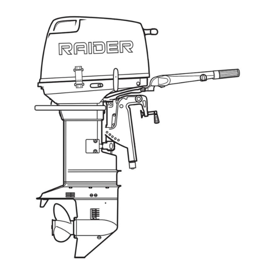
OMPONENTS AND ONTROLS 1. Tilt Handle 10. Propeller 19. Reverse Lock Lever 2. Cowling 11. Skeg 20. Throttle Tension Adjust 3. Cowling Strap 12. Oil Plug (Lower) 21. Dewatering Lever 4. Cowling Latch 13. Water Strainer 22. Shift Lever 5. Tell-tale 14. - Page 21 RAIDER 55 Components Cowling A removable cover of the outboard engine that provides protection for the powerhead and components during operation and storage. Cowling Latch A mechanism located on the rear portion of the lower engine cover that provides a means to secure the cowling in place.
- Page 22 Tiller Arm Mechanical lever the attaches to the swivel bracket that allow the operator to steer the craft to port or starboard. Also provided the mounting structure for the Throttle Control and Throttle Tension Adjustment. Throttle Control Affixed to the end of the Till Arm. Allow the operator to control the acceleration and deceleration of the engine.
- Page 23 Ensure that the throttle is at idle before placing the engine into gear. Tachometer/Hour Meter Displays the total number of hours the RAIDER Model 55 Outboard Engine has been operational. Tachometer mode may be selected by the operator to monitor engine...
- Page 24 Engine Stop Push Button/Kill Switch Located on the front of the lower engine cover. Push button switch that when pressed will shut the engine down. Lock Plate and Lanyard The lock plate must be attached to the engine stop switch for the engine to start and remain running.
- Page 25 Stern Brackets Used to mount the engine to the transom plate. C-shaped clamps that slide over the transom for the purpose of securing the engine for operations. Reverse Lock Lever A two-position lever, located on the right side of the Swivel Bracket.
- Page 26 Stern Bracket Anode Made of zinc a highly active metal that attracts electrolytes that would normally corrode and weaken the less active metal. Oil Level Plug Located just beneath the AV-Plate on the forward portion of the Gearcase. When open it release vacuum in the Gearcase to allow oil to drain freely from the Lower Fill/Drain hole.
- Page 27 Water Strainer (Set) Located on both sides of the Gearcase. A fabricated beveled opening covered by a plastic screen that allows for the intake of water by the impeller for cooling. This is simply a small plastic basket that is tapered and has perforation holes which acts as a filter for larger debris.
-
Page 28: Systems Details
NTAKE AND XHAUST YSTEM The Intake and Exhaust System of the RAIDER Model 55 Outboard Engine is comprised of two sets of components, the intake and the exhaust. The intake side of the system is designed to allow air to be drawn into the engine so that... - Page 29 Intake and Exhaust System Components Cowling A series of circular baffles are integrated into the upper- rear portion of the cowling. These baffles are designed to allow fresh air to pass into the cowling while preventing most water from entering. Does not prevent water from entering during submersion.
- Page 30 Reed Valves Set of flexible metal flaps which act as one-way valves. The flaps are free to bend forwards into the intake, allowing air-fuel mixture to enter cylinder. As the compression stroke occurs, the pressure from inside the cylinder forces the reed valves back the other way, closing them and preventing exhaust gasses from traveling backwards through system.
- Page 31 Exhaust Pipe Directs exhaust gas from the combustion chamber to the gearcase, where it exits the engine through either the exhaust ports or the propeller hub. Through-Hub Exhaust Allows exhaust to exit the engine through the propeller hub, allowing the propeller spin more easily at lower speeds.
-
Page 32: Fuel System
YSTEM The Fuel System of the RAIDER Model 55 Outboard Engine is designed to store fuel and to deliver that fuel to the engine’s combustion chamber where it is combined with air, compressed, and ignited in order to power the engine. - Page 33 Fuel Pump Force fuel through the fuel system. The pumps contain internal diaphragms that move in response to crankcase pressure. This changing pressure causes fuel to be drawn in and pumped out through a series of one-way valves, ensuring fuel is moved in the correct direction. Carburetors Responsible for introducing the fuel to incoming air.
-
Page 34: Electrical System
LECTRICAL YSTEM The RAIDER Model 55 Outboard Engine’s electrical system is comprised of the Ignition System. The Ignition System is responsible for providing the electrical spark which ignites the compressed air-fuel mixture in the combustion chamber. Electrical System Components Flywheel/Magneto... - Page 35 Exciter Coil Works similarly to the alternator coil, but part of the ignition system. Provides power to the CD unit. Trigger (Pulser Coil) Part of the ignition system, the trigger detects the position of the crankshaft and relays the information to the CD unit.
- Page 36 Ignition Cable Responsible for conducting the voltage from the ignition coil to the spark plug with as little resistance as possible. Spark Plug Part of the ignition system, one spark plug per cylinder is threaded into the head of the engine. The stainless-steel spark plugs are responsible for igniting the air-fuel mixture using electricity supplied by the ignition system.
-
Page 37: Drive System
RIVE YSTEM The RAIDER Model 55 Outboard Engine Drive System is comprised of the set of components responsible for capturing the energy produced in the combustion chamber, and transferring that energy to the propeller to generate thrust. The Drive System can be divided into three main subsystems, the Crankcase, the Gearcase, and the Gear Shifter. - Page 38 Drive System Components Engine Block/Crankcase Cover Houses combustion chamber, pistons, crankshaft. The crankshaft assembly is held in place by the crankcase cover. Cylinder Head/Cylinder Head Cover Two-part cylinder head houses the spark plugs, thermostat, and decompression valves. Acts as the ‘top’ of the combustion chamber, containing the air-fuel mixture as it is compressed and ignited, and directing the energy of the resulting combustion towards the piston.
- Page 39 Flywheel Connected to the crankshaft at the top of the engine, the flywheel stores some of the rotational energy from the crankshaft as inertia. This inertia allows the crankshaft to continue rotating as the piston reaches the bottom of the power stroke.
- Page 40 Prop Shaft Housing Mounted inside the gearcase, secures the prop shaft in place and houses the prop shaft roller bearing and the forwards gear ball bearing. Forwards/Reverse Gears Opposite-facing gears mounted concentrically along the prop shaft. Selected by actuation of the shift handle. Clutch Dog Slides between the forwards and reverse gears engaging one or the other depending on the position of the shift...
- Page 41 Propeller Three-blade, aluminum construction. Able to absorb impact energy to protect drive components. Shift Handle Mounted on the side of the engine pan, allows the operator to select between forwards, neutral, and reverse. Shift Linkage Series of rods and levers, including the shift rod and cam rod, which actuate the clutch dog.
- Page 42 Clutch Cam Stepped cam attached to the end of the cam rod. Actuates the clutch dog.
-
Page 43: Cooling System
The Cooling System of the RAIDER Model 55 Outboard Engine is designed to provide cooling to the engine block by pumping cool, raw water through the engine. This... - Page 44 Cooling System Components Water Intake The opening through which the water pump draws water into the gearcase. A screen across the opening prevents foreign matter such as grass, sticks, and small rocks from entering the system, as this could plug the cooling passages and destroy the engine through overheating.
- Page 45 Thermostat Cap Removable cover which allows access to the thermostat for servicing. Bolts must be re-torqued after removal to prevent water from leaking. Thermostat Cap Gasket Ensures proper seal of thermostat cap. Must be replaced if thermostat cap is removed. Water Jacket Passageways inside the engine block and cylinder head through which cooling water flows.
- Page 46 Tell-tale Small opening which emits a stream of water, indicating that the water pump is functioning correctly. If little or no water is being discharged from the check port, check whether the intake screen is clogged. This is not the primary exit for cooling water, as most of the water leaves the engine through the exhaust ports.
-
Page 47: Prior To Operation
RAIDER 55 Operator’s Manual Prior To Operation EQUIREMENTS Fuel is flammable and harmful to health. Keep fuel away from heat or ignition sources. DO NOT smoke within 50 feet (15 m) of a fuel source. Do not work on fuel system when engine is hot. - Page 48 Use gasoline only when operating the RAIDER Model 55 Outboard Engine. Use a major brand of Marine Fuel Stabilizer with ethanol treatment. STA-BIL 360® MARINE™ is recommended for added internal engine cleanliness and conditioning the fuel system to ward off corrosion.
- Page 49 The following will instruct you on how to properly mix fuel for the RAIDER Model 55 Outboard Engine: Gasoline requires a 50:1 Fuel to oil mixture. 16oz of oil per six (6) gallons of fuel or about 2.5oz per one (1) gallon.
- Page 50 Shake the bladder or tank to mix the marine oil and gasoline well and even. Annotate the date of the mixture. Fuel older than 90 days should be disposed of via required hazardous materials disposal instruction for your organization.
-
Page 51: Break-In
Operating the Outboard Engine without break-in can shorten service life of the product. If any abnormality is experienced during the break-in: Discontinue the operation immediately. Contact Raider Outboards Technical Support for action(s) if necessary. Proper break-in allows Outboard Engine to deliver full performance for longer service life. -
Page 52: Engine Mounting
NGINE OUNTING The outboard engine weighs approximately 163.5 lbs. (74.2 kg). A minimum of 5 personnel and proper lifting techniques are recommended to lift, move, or carry engine. Failure to comply to this warning could result in injury to personnel. Do not operate the Outboard Engine until it has been securely mounted on the boat in accordance with the instructions below. - Page 53 These plates provide a guide for the stern bracket of the engine that will automatically center the Raider 55 to the center line of the craft. Then simply tighten the stern bracket screws. After 10-15 minutes of operation recheck the stern...
-
Page 54: Dual Engine
NGINE Dual Linkage/Transom Plate applies to Inflatable Combat Assault Craft, I-CAC (15 Person Craft) only The Dual Engine Transom Plate is only used during the operation of two (2) RAIDER 55HP Engines. Do not try to center a single engine using the Dual Transom Plate. The Dual Linkage Kit and Dual Engine Transom Plate are both required to operate the I-CAC using dual RAIDER 55HP Engines. - Page 55 The following steps will instruct you on installation of the Dual Engine Transom Plate. The Dual Engine Transom Plate kit for the I-CAC contains a transom plate and five (5) screws. Remove existing transom by removing the five (5) screws using a Phillips head screw driver. Retain both the transom and screws for operation of a single engine.
-
Page 56: Dual Engine Mounting
With the provided five (5) screws alternate screwing in the Dual Engine Transom in place. With the transom correctly installed you are ready to mount the two engines. See Dual Engine System Installation Guide for additional instructions NGINE OUNTING The following steps will instruct you on mounting engines with the Dual Engine Transom Plate. - Page 57 Centering the engine over position both stern bracket clamps into premade groove. Hand-tightened the two (2) stern bracket clamps. Attach safety cable (lanyard) to secure the engine to the craft and prevent the engine from dropping from the stern if the clamps get loose or fail during operation.
-
Page 58: Dual Linkage Kit Installation
INKAGE NSTALLATION Dual Linkage/Transom Plate applies to Inflatable Combat Assault Craft, I-CAC (15 Person Craft) only The Dual Engine Transom Plate is only used during the operation of two (2) RAIDER 55HP Engines. Do not try to center a single engine using the Dual Transom Plate. The following steps will instruct you on how to install the Dual Linkage Kit: With both engines mounted on the Dual Transom Plate. - Page 59 Remove the two (2) 14 mm bolts from underside of front grab handle and retain for installation. NOTE: Grab handle will become loose. 14 mm steering arm Insert the two (2) bolts into the extension. Apply blue threadlocker to each bolt. steering arm Reattach front grab handle and extension...
- Page 60 Remove the 10mm bolt and the front cover plate. Insert the Dual Linkage tiller arm into the right most steering arm extension. Insert the round wire lock pin and fasten...
- Page 61 Insert the short push pull cable into cable control mount and tighten. Insert the cable control mount into the engine. The two (2) bolt holes will line up and the mount will rest against the air intake frame.
- Page 62 Secure the cable control mount using the provided bolts and washers. A larger washer is provided for the rear most bolt. Adjust throttle control as needed, connect the throttle cable end to the throttle advancer arm. Tighten the two (2) 10 mm bolts on the cable control mount.
- Page 63 Using the long push pull cable repeat steps 10 through 15 with second engine. Attach the steering rod mount to left engine steering arm extension and secure with retaining pin.
- Page 64 Attach steering rod to both ball connectors on the underside of the steering rod mount and tiller arm. Reinstall air box covers on both engines. Reinstall both engine cowlings and reinsert both safety lanyards.
-
Page 65: Propeller Selection
ROPELLER ELECTION The RAIDER Model 55 Outboard Engine is shipped with the propeller item listed in the parts list. This propeller is designed for an average load. A propeller must be selected so that the engine rpm measured at wide open throttle while cruising is within the max. -
Page 66: Standard Operating Procedure
RAIDER 55 Operator’s Manual Standard Operating Procedure RAIDER M 55 O TARTING THE ODEL UTBOARD NGINE The primary means to start the engine is by using the recoil starter. The recoil starter is mounted to the top of the powerhead with the T-Handle pull cord grip fed through the opening in the forward part of the engine cowling. - Page 67 • Do not shift to "F" or "R" until engine is at proper idle speed. The following steps will instruct you on how to start the RAIDER Model 55 Outboard Engine: Connect the fuel connector to the engine Feed fuel to the carburetor by squeezing the primer bulb until firm.
- Page 68 Set the shift lever to Neutral Turn the throttle grip so that the indicator line meets the "START" mark. Ensure dewatering lever is fully forward and locked into position. Pull the starter rope slowly until resistance is met. Give it a sharp tug to start the engine. Turn the handle grip to its original position gradually once the engine has started.
- Page 69 Carefully turn the throttle grip to "SLOW". Let the engine run at idle for approximately three minutes for warm prior to placing under load. This will ensure all moving surface are at optimal operating temperature and properly lubricated. Immediately placing under load after start will significantly shorten engine life.
-
Page 70: Maneuvering
ANEUVERING • Never stop the engine immediately after a full throttle run. Keep it running for two or three minutes at idling speed (Shift Lever set to Neutral) to allow it to cool down. • Before moving the Shift Lever to Reverse, make sure the Reverse Lock is engaged (in up position). -
Page 71: Trim Adjustments
DJUSTMENTS Excessive trim up or down may lead to unstable boat operation, potentially causing the steering difficulty that leads to accident during cruising. When testing a trim position, run boat slow initially to see if it can be controlled safely. •... - Page 72 In general, the Raider 55 HP trim should be set to the second hole from the bottom. However, this does not preclude the Operator from assessing load and prevailing sea conditions and...
-
Page 73: Shallow Water Running/Beaching
HALLOW ATER UNNING EACHING During shallow water operation, be careful not to place your hand between the swivel bracket and the stern bracket. Be sure to tilt the outboard down slowly. • Run at lowest possible speed during cruising using shallow water drive. •... -
Page 74: Dewatering
EWATERING The RAIDER Model 55 Outboard Engine upon recovery to the surface may be fully operational within 10 minutes. Easy instructions for dewatering are provided affixed to the cowling of every outboard engine. Most Operators, with practice and adherence to the provided instructions, restore the engine to operations within two (2) minutes of surfacing. -
Page 75: Pre-Submersion
Dewatering Valve Push button valve located inside the right side of the lower engine cover. When actuated, the Dewatering Valve opens the drain line from the bowl of the carburetor, providing a discharge path for bad fuel to be expelled overboard from the system. - Page 76 • Connect fuel line and pump primer bulb until firm resistance is felt to fill fuel system. The following steps will instruct you on how to perform the Dewatering procedure: Secure the engine in the run position. Remove safety lanyard and place shift lever in NEUTRAL position.
- Page 77 Make sure the fuel line is connected and squeeze the Primer Bulb 5 – 10 times until water clears from fuel line overboard. Push the Dewatering Valve back to the closed position. Squeeze the primer bulb until firm.
- Page 78 Pump the engine primer five (5) times. Turn the throttle 1/2-inch past normal start position. Reinsert the emergency stop switch lanyard. Start engine. If engine fails to start pump primer three (3) more times...
-
Page 79: Post Submersion
Engineered specially for the harsh coastal climates, prevents corrosion, cleans the fuel system, and prevents the buildup of unwanted gum and varnish, mitigating the adverse effects of submerging your RAIDER Model 55 Outboard Engine. • After the 30-minute run period, disconnect the fuel supply with the engine running and... - Page 80 Compressed air used for cleaning purposes must not exceed 30 psi (207 kPa). Wear gloves and eye protection. Do not direct compressed air at yourself or other people. Failure to comply may cause injury to personnel. • Using Low Pressure (LP) air, if available remove excess water from the surfaces of the powerhead.
-
Page 81: Flushing
LUSHING The following steps will instruct you on how properly Flush the RAIDER Model 55 Outboard Engine: Attach flush kit “ears or flush connector” to a hose connected to a water source. Connect the flushing kit to the two (2) water intakes located on the lower unit. - Page 82 Prime the engine 3 – 5 times. Three (3) if engine was used earlier that day, five (5) if you haven’t used it. Attach the safety lanyard Start the engine. Operate the for approximately five (5) minutes at full operating temperature. A steady stream of water will discharge from the tell-tale.
- Page 83 Disconnect the fuel supply and let the engine run itself dry. Turn off water and remove flush kit.
-
Page 84: Long-Term Storage (Layup)
TERM TORAGE AYUP For extended periods of nonuse or long-term storage, typically 90 days or more, placing the engine into a Layup condition is highly recommended. This process adds the needed layer of oil residue onto all the interior parts preventing corrosion and removes residue from the breakdown of fuel that clogs fuel system components. - Page 85 Attach Mixing Unit to a hose connected to a water source. Attach the Flush Unit to mixing unit. Thread until tight Fill mixing unit with corrosion preventive according to manufacturing instructions. Attach flush unit to the water intake screens on the lower unit.
- Page 86 Attach fuel line and pump bulb until firm allowing fuel to enter into the carburetor bowls. Turn on water. Run the engine at a fast idle to circulate treated fuel throughout the filter and carburetor(s). Once engine has reached operating temperature, set the mixing unit mixing selector to the “Salt- Away"...
- Page 87 With engine idling, disconnect fuel supply. Engine will run on just the treated fuel in the carburetor float bowl(s). As engine starts to die, rpm will climb. At this precise moment, begin squirting fogging oil down the carburetor throat for 3-5 seconds. Repeat for each carburetor.
- Page 88 Apply dielectric grease to plug boot and reattach to respective spark plug. Repeat for each spark plug (3). Reinstall the air box cover Spray Powerhead with Corrosion Preventative protecting all external metal parts. Install cowling. Turn off water and remove mixing unit and flush kit...
- Page 89 Stow engine inside a dive locker/boat shop, garage, or storage container.
-
Page 90: Troubleshooting
Troubleshooting Troubleshooting Guidelines When troubleshooting any malfunction, the root cause of the issue should be investigated prior to performing any repair actions. Unless the fundamental source of the problem is identified and corrected, similar malfunctions will continue to occur. Before disassembling or replacing any components or making any adjustments to the engine, be sure to note the following: 1. - Page 91 Troubleshooting Matrix. Continue this procedure until the problem no longer occurs. 6. If the problem persists after exhausting all solutions provided in the Troubleshooting Matrix, seek the next level of technical support within your organization, or contact Raider Outboards Technical Support. D. Common Performance Issues 1.
- Page 92 g. Is the fuel tank/bladder vent open? Open vent screw. h. Has the fuel pump malfunctioned? Remove cowling, visually inspect fuel lines for fuel flow. i. Are spark plugs fouled or incorrect type? Inspect spark plugs. Clean or replace with recommended type. j.
- Page 93 c. Is the fuel contaminated or stale? Fill tank/bladder with fresh, clean fuel. d. Is the fuel oil mixture too rich or too lean? If blue smoke is coming out of the exhaust or if oil is dripping from the exhaust, the fuel ratio is too rich.
- Page 94 d. Are the stern bracket clamp screws loose? Inspect and tighten screws. 5. Engine Power Loss a. Is the propeller damaged? Have propeller repaired or replaced. b. Is the trim angle incorrect? Adjust trim angle to achieve most efficient operation. c.
- Page 95 If you encounter a problem with the engine, check the list below. Locate the problem you are experiencing, then follow the suggested remedies. Do not hesitate to contact Raider Technical Support, as professional advice and assistance is the best way to keep the engine in optimum condition. Unstable engine Abnorm-...
- Page 96 Unstable engine Abnorm- Abnorm- Cannot Difficult to Engine Over- running ally high ally low obtain high start starts, but Poor Idling heating of speed or engine engine engine engine stops soon engine engine speed speeds speeds speed ● ● ● Propeller cavitation ●...
-
Page 97: Preventive Maintenance Checks And Services (Pmcs)
As the Operator or Field Service Technician (FST) you must be intimately familiar with the Before and After Operations Checks for the RAIDER Model 55 Outboard Engine. Preparing the engine for an operational period is the most critical part of mission execution. These actions directly contribute to mission success and when ignored will lead to reduced reliability, engine casualties, or mission failure. -
Page 98: Before Operations Checks
EFORE PERATIONS HECKS • Grease contains ingredients that can cause mild skin contact hazard. Treat random or occasional skin contact with mild soap and water. Gloves and eye protection is required with heavy, constant exposure. Do not ingest. • Immediately clean up any spilled compound. Comply with local procedures and environmental regulations when disposing of grease or cleanup materials. - Page 99 of power from the engine to the propeller shaft. Lower Unit: Any indication or the presence of gear oil leaking form the oil fill, oil drain, and bearing cap. Structural damage in the form of holes, cracking, gouging, impacts, abrasions that result in gear oil leakage.
- Page 100 corrosion, lack of Should the wire shielding present maintenance, or damage that exposes bare wire. abuse. Cable BEFORE Verify the Cable Cable Lanyard missing. Lanyard Lanyard is securely attached to the engine and may be securely attached to craft Transom. Shift Lever BEFORE Inspect for damage...
- Page 101 Recoil Starter BEFORE Inspect for damage Any condition that would prevent the due to corrosion, lack mechanical mechanism from of maintenance, or operating. abuse. Starter handle is missing or damaged. Starter rope is torn, broken or frayed. Starter Lock BEFORE Inspect for damage Cable Lanyard missing.
- Page 102 This item is organization dependent, as cap, vent, or rip in Raider Outboards does not supply tank membrane. Inspect or bladder systems. securing straps: Ensure the bladder can be adequately secured to the deck.
- Page 103 Fuel Line BEFORE Inspect end Equipment not available if fuel leak of Assembly connectors: Check any type is present. ensuring proper fit and seal to bladder and engine. Inspect fuel line: Check for dry rot and leaks. Inspect bulb: Check for proper installation, dry rot, and function.
-
Page 104: During Operations Checks
or excessive wear. Inspect Lines: Check for dry rot and chaffing. Primer BEFORE Inspect for damage Equipment not available if fuel leak of due to corrosion, lack any type is present. of maintenance, or abuse. Loose ball joints, locknuts, bent link rods, loose rod snaps. - Page 105 freely to port and starboard. Neutral DURING Verify the propeller The Shift Lever should smoothly shift does not engage between forward, neutral, and reverse when the gear and remain in selected position. selector is in the neutral position. Should the Shift Lever and or linkages present damage that prevent smooth gear selection, or the Shift Lever will not remain in selected position.
-
Page 106: After Operations Checks
lift the lower unit past a 45° angle until the tilt stopper assembly locks. Full Tilt DURING Move the engine Engine can not be tilted. Tilt support Position Reverse Lock Lever to lock does not engage or disengage. the release position, lift the Lower Unit past a 90°... - Page 107 submersion period the engine must be run at operating temperature for no less than 30 minutes to ensure all water is removed from the head. Disconnect the fuel supply and let the engine run itself dry. Any area of the engine has significant Wipe Down AFTER Use Low Pressure...
- Page 108 Latch handle and shaft assembly missing or damaged. Wires are damaged, chaffed or corroded. Connections are loose, dirty or corroded.
-
Page 109: Operator Maintenance And Repair Procedures
Operator Maintenance and Repair Procedures The following section is intended to provide operators of the RAIDER Model 55 Outboard Engine with step-by-step instructions on how to maintain and repair each relevant item included on the “Recommended Parts List Per Engine”. For a complete “Recommended Parts List Per Engine”, please reference the “Appendices”... - Page 110 Remove Stinson Fingers Using a modified 13 mm socket, located in the emergency toolkit, remove decompression valve. Apply copper anti-seize onto threads of new decompression valve. Insert valve and tighten to a torque of 15ft/lbs. Ensure washer and spring remain on McQuaig Rod before installing Stinson Fingers.
- Page 111 Reinstall Stinson Fingers. Reinstall lower shoulder bolt and nut. Ensuring dewatering lever is closed (forward) reinstall McQuaig Rod 8mm nut. Tighten electrical box cover.
-
Page 112: Spark Plugs
PARK LUGS Remove plug caps and then using a 3/8 socket remove spark plugs. Obtain new spark plug gapped at 0.035in and apply copper anti-seize to threads. Install spark plug, torqued to 20ft/lbs. NOTE: If a torque-wrench is not available when you are fitting a spark plug, a good estimate of the correct torque is 1/4 to 1/2 a turn past finger-tight. - Page 113 Remove air intake silencer box cover. Using a flat head screw driver, bend down all six (6) tabs holding the locking plate bolts. With an 8mm wrench or Phillip’s head screwdriver loosen the six (6) bolts holding the locking plates in place.
- Page 114 Remove carburetor ensuring O-ring attached. Remove the four (4) Phillip’s head screws holding the float chamber. Replace Float Chamber Gasket, gasket only sits one way. Reinstall Float Chamber Reinstall carburetor, air intake, and air intake cover...
-
Page 115: Primer
RIMER Obtain new Primer. Drain fuel in engine. Dispose of contaminated drained fluids IAW the Standard Operating Procedures (SOP) of your unit. Remove air intake silencer. Cut the two (2) zip ties and disconnect the two (2) fuel lines connected to the Primer. - Page 116 Remove the 7/8 nut and washer from the Primer. Remove old Primer Unthread washer and nut from new Primer. Insert new Primer with angled fuel line connector facing left. Reinstall washer and nut. With needle nose pliers gentle bend right side fuel line connector.
-
Page 117: Fuel Filter Element W/O-Ring
Reinstall the two (2) fuel lines and fasten with zip ties. Remove any excess zip tie. Reinstall air intake and air intake cover. W/O-R ILTER LEMENT If water is in the cup. Remove the cup and drain the water. Obtain replacement Fuel Filter and O-Ring. Using a 13 mm wrench loosen the nut holding the Fuel Filter to the engine. - Page 118 Place container under fuel filter. Twist off fuel filter cup, pouring any excess fuel into container. Dispose of contaminated drained fluids IAW the Standard Operating Procedures (SOP) of your unit. Remove old O-Ring and fuel filter. Retain fuel filter cup. Insert new O-Ring and fuel filter into fuel filter cap.
-
Page 119: Starter Lock
Tightly screw in fuel filter cup. Reconnect fuel filter to engine. Ensure the two washers connect with engine. Tighten nut. TARTER Remove electrical box. - Page 120 Trace Starter Lock wire to CD Unit and disconnect from starter lock arm using needle nose pliers. Remove and collect the three (3) bolts and washers holding the flywheel cover. Release starter lock wire from CD Unit and remove fly wheel cover.
- Page 121 With needle nose pliers remove split pin from Starter Lock. Remove washer and Starter Lock. Release Starter Lock Cam from spring. Replace all nonfunctioning part(s).
- Page 122 Install Starter Lock wire into flywheel cover. Ensure wire clamp and spring are properly set in tab. Install Starter Lock spring and Starter Lock. Holding Starter Lock spring. Insert Starter Lock Cam from underneath flywheel cover.
- Page 123 Release Starter Lock spring into Cam groove, holding in place. Install washer and pin. Using needle nose pliers bend ends in place. Reinstall flywheel. Apply blue thread locker and install the three (3) bolts and washers.
- Page 124 Reinstall the Starter Lock wire. Reinstall Starter Lock wire clamp into starter lock arm using needle nose pliers. Reinstall electrical box.
-
Page 125: Starter Rope
TARTER To remove the fly wheel cover, first remove electrical box cover. Retain parts for later installation. Trace Starter Lock wire to CD Unit and disconnect from starter lock arm using needle nose pliers. Remove and collect the three (3) bolts and washers holding the flywheel cover. - Page 126 Remove fly wheel cover. With a flat head screwdriver remove the plug from the pull handle. Untie pull rope knot and remove handle. Remove rope to fly wheel. Locate fly wheel notch. Holding rope in notch rotate fly wheel clockwise until spring tension released (approximately three (3) times).
- Page 127 Using a Phillip’s head screw driver remove the metal clamp and screw. Retain for later installation. Remove and retain wire retainer ring. Carefully lift and remove fly wheel. Unwind rope clockwise and remove.
- Page 128 With replacement rope tie a knot in one end. Feed other end through fly wheel leaving knotted end in notch. Wrap rope counter clockwise leaving the end notched.
- Page 129 With spring side up insert fly wheel and turn counter clockwise until notch in fly wheel sets with notch in spring. Fly wheel will be flush with cover. Sit wire retainer ring outside of tabs with end inserted into spring loop. Align metal clamp with tabs and install Phillip’s head screw until tight.
- Page 130 Wind fly wheel counter clock wise until tension causes fly wheel to cock back. Then continue to turn counter clockwise another three (3) turns. Holding fly wheel in place, feed rope through the loops. With rope installed test fly wheel tension by pulling and releasing starter rope.
-
Page 131: Oil Fill/Drain Gasket
Reinstall plug into pull handle. RAIN ASKET Position oil drain pan under the lower unit. With a flat head screwdriver remove oil fill plug and washer (drain gasket). Retain plug for reassembly and discard washer. Remove oil level plug to release vacuum, allowing oil to drain freely. -
Page 132: Anode, Trim Tab
To fill oil, attach lower unit pump via connector at fill port. Pump until gear oil flows from oil level port. Replace oil level plug and washer. Washers should be replaced every oil change. Remove lower unit pump from oil fill port. Replace the oil fill plug and washer. - Page 133 Anodes must be replaced when they have been reduced to 2/3 of their original size. Engine corrosion will increase if eroded anodes are not replaced. Do not paint or coat anodes or their mounting surfaces. Lightly coat external anode bolt threads with anti- seize.
-
Page 134: Propeller Assy (11Pcv)
(11PCV) ROPELLER • Before removing or installing propeller, be sure to remove stop switch lock plate. • When removing or installing propeller, do not handle propeller with bare hands. • Put a piece of wooden block between anti-cavitation plate and propeller to prevent rotation of propeller when removing or installing propeller. - Page 135 Use flat-head screwdriver to pry up and lift off thrust washer. Retain for reassembly. Carefully scrutinize propeller blades for damage. Dings and missing chunks are easy to spot, but a slightly bent blade may not be readily apparent. You can often feel it when underway because it usually creates vibration Looking at prop from side makes it easier to spot a bent blade...
- Page 136 Install propeller over propeller shaft. Use 22mm socket and to tighten propeller nut. Do not over-tighten nut. Install washer.
- Page 137 Using a 22mm socket install propeller nut. Do not over-tighten. Ensure alignment of nut and pin bolt hole. Insert split pin through propeller nut and use needle nose plyers to bend ends into place...
-
Page 138: Anode, Stern Bracket
NODE TERN RACKET Anode protects outboard engine from galvanic corrosion. Do not paint or apply grease or oil to anode. Doing so disables the anode. With a 10mm socket, loosen bolt that retains sacrificial anode on bottom of stern bracket. Retain bolt and washer for reassembly. -
Page 139: Stop Switch Lanyard Assy
WITCH ANYARD Obtain replacement Stop Switch Lanyard Assembly. Remove the six (6) Phillip’s head screws from the electrical box cover. Retain screws and box cover for later installation. Trace the Stop Switch wire to its connection with the CD Unit. Clip and remove the two (2) zip ties holding the Stop Switch and CD Unit wire connectors. - Page 140 Unscrew and release the Stop Switch ground wire. Using needle nose pliers remove the 7/8 nut from the Starter Switch Assembly located near the front grab handle. Replace Starter Switch Assembly, then using needle nose pliers install the 7/8 nut to hold the assembly in place.
- Page 141 Regrease CD Unit wire end connector. Reconnect Start Switch wire end connector to CD Unit connector. Zip tie connections to hold in place and remove any excess tie. Reinstall electrical box cover using the six (6) Phillip’s head screws.
-
Page 142: Fuel Line Replacement Kit
EPLACEMENT Fuel Line Replacement Kits contains precut lines, ties, clamps and a parts list. Locate the fuel line to be replaced Follow the line to both end points and cut any ties and/or remove retention bands or hose clamps. Remove broken fuel line. Identify the replacement piece from the item description and the length of hose removed. - Page 143 Replace with the new hose. Replace any ties, retention bands and clamps. Securing any loose ends.
-
Page 144: Stern Bracket Clamp Screw Kit
TERN RACKET LAMP CREW To remove, remove retainer bolt. Remove back plate. Unscrew and remove clamp screw. Reverse steps for installation. -
Page 145: Thermostat And Thermostat Cap Gasket
HERMOSTAT AND HERMOSTAT ASKET To remove, loosen and remove 3x 10mm thermostat cap bolts with 10mm socket. Retain for reassembly. Remove thermostat cap and gasket Discard gasket and retain cover for reassembly. Remove and discard thermostat. - Page 146 With a razor blade remove old gasket from thermostat cap and cylinder head. Obtain new thermostat and gasket. Lightly coat thermostat sealing surface with marine grease to aid in placement inside cylinder head. Insert thermostat into cylinder head. Align gasket with bolt holes. Align the thermostat cap with the bolt holes.
-
Page 147: Tachometer
ACHOMETER When the engine is started, the display will indicate the RPM of the engine. When the engine is shut down, the display will show hours and minutes. Operating 1. Push “SELECT” button several times until display shows “1P1r”. DO NOT RELEASE BUTTON until “SET”... - Page 148 1. Push “SELECT” button four times, the display will show “SVC”, do not release button until “SET” appears “5:00” is flash. Then can to set. The “SVC” degree is 5 to 50 hours. SVC & 2. Push “SELECT” button five times, the display SVC2 will show “SVC2”, do not release button until “SET”...
- Page 149 This product has two versions about wire (installation). Function is the same.
-
Page 150: Appendices
Number: Operation: Before placing the RAIDER Model 55 Outboard Engine into service and or starting the engine, complete the checks listed in the Before Operations Checklist. The Before Operations Checklist is designed to ensure that the engine and all systems are in proper working order to support engine operation, and to ensure safe and efficient boat operation. - Page 151 • Inspect for damage due to corrosion, lack of Shift Lever Mechanism maintenance, or abuse. Loose ball joints, locknuts, and Shift Lever Stopper bent link rods, loose rod snaps. • Inspect for damage due to corrosion, lack of maintenance, or abuse. Loose ball joints, locknuts, Throttle Linkage bent link rods, loose rod snaps.
- Page 152 Completed Fuel System Checks (initial) • Requires a 50:1 fuel to oil mixture. 16oz per six (6) gallons or about 2.5oz per every one (1) gallon. • Use only NMMA TC-W3 2-Cycle Synthetic Marine Oil. Gasoline Fuel Mix Ratio • Use STA-BIL 360®...
-
Page 153: During Operations Checks
URING PERATIONS HECKS During Operations Checks Completed (initial) • Pull Start Start the engine using the recoil starter. • Neutral Safety Verify that the engine will not start in gear both forward and reverse. • Water discharge from When the engine is running verify that water is being check ports discharged from all check ports. - Page 154 Notes and Discrepancies...
-
Page 155: After Operations Checklist
FTER PERATIONS HECKLIST Engine Serial Date of Engine Hours: Number: Operation: Complete the checks listed in the post-operational checklist. The post-operational checklist is designed to ensure all systems are secured properly and the boat is prepared for future missions. Completed After Operations Checks (initial) •... - Page 156 Notes and Discrepancies...
- Page 157 ECOMMENDED ARTS NGINE CAGE Part No. Description R400921 Decompression Valve 595K1 R500151 Spark Plug 595K1 Float Chamber Gasket 595K1 R500418 Primer 595K1 R500521 Fuel Filter Element W/O-Ring 595K1 R500541 Starter Rope 595K1 R500711 Starter Lock 595K1 R500715 Oil Fill/Drain Gasket 595K1 R501406 Anode, Trim Tab...
- Page 158 ONSUMABLE ATERIAL EQUIREMENTS Item Part No. CAGE Anti-Seize Lubricant 77164 5972 Carb/Throttle Cleaner 777185 1UVT5 Corrosion Preventative 90104 0VJ14 Dielectric Grease DC4-2OZ 71984 Flange Sealant AT412 48CF5 Fogging Oil 777186 1UVT5 Fuel Stabilizer 766210 1UVT5 Gear Oil, API Grade GL-5, SAE 80W-90W J2360 0U583 Instant Adhesive...
Need help?
Do you have a question about the 55 and is the answer not in the manual?
Questions and answers