Table of Contents
Advertisement
Quick Links
Product Service Manual – X193HQL
Service Manual for acer: X193HQL
P/N: 9J.0NA15.81A
Applicable for All Regions
Version: 001
Date:2009/9/3
Notice:
- For RO to input specific "Legal Requirement" in specific NS regarding to responsibility and liability
statements.
First Edition (Auguest, 2009)
© Copyright Acer Corporation 2009. All Right Reserved.
- 1 -
Advertisement
Table of Contents

Related Manuals for Acer X193HQL


Summary of Contents for Acer X193HQL
- Page 1 Applicable for All Regions Version: 001 Date:2009/9/3 Notice: - For RO to input specific “Legal Requirement” in specific NS regarding to responsibility and liability statements. First Edition (Auguest, 2009) © Copyright Acer Corporation 2009. All Right Reserved. - 1 -...
-
Page 2: Table Of Contents
Content Index Abbreviations & Acronyms ................3 1. About This Manual ..................3 1.1. Trademark ......................3 2. Introduction ....................4 2.1. RoHS (2002/95/EC) Requirements ..............4 2.2. Safety Notice ....................4 2.3 .Compliance Statement ..................5 2.4. General Descriptions ..................5 3. -
Page 3: Abbreviations & Acronyms
Abbreviations & Acronyms 1. About This Manual This manual contains information about maintenance and service of acer products. Use this manual to perform diagnostics tests, troubleshoot problems, and align the acer product. 1.1. Trademark The following terms are trademarks of Acer Inc. :... -
Page 4: Introduction
2. Introduction This section contains general service information, please read through carefully. It should be stored for easy access place for quick reference. 2.1. RoHS (2002/95/EC) Requirements – Applied to all countries require RoHS. The RoHS (Restriction of Hazardous Substance in Electrical and Electronic Equipment Directive) is a legal requirement by EU (European Union) for the global electronics industry which sold in EU and some counties also require this requirement. -
Page 5: Compliance Statement
3. Product Overview 3.1. Introduction X193HQ is defined as our new 18.5W model in ACER X series which will be the ACER project in Qisda. X193HQ is defined as 18.5”W LCD Monitor supports 1366(H) x 768(V) resolution with DPMS (Display Power Management System) and ACER eColor function. There are triple input types, D-sub, DVI. - Page 6 connector HDMI interface with Scaling supported For 1A1D model Max resolution mode supported 1366 (H) x 768 (V)@60Hz Number of Display Colors supported 16.7 Millions Test Condition: Set Contrast 1000:1 (typ.),600:1(min) Contrast Ratio at 50, Brightness at 100, Color at User preset AUO M185XW01 V7 Test Condition: Set Contrast Luminance...
-
Page 7: Operational Specification
Mechanical Lift base design Kensington compatible lock design 3.2. Operational Specification 3.2.1 Power supply Item Condition Spec OK N.A Remark Input Voltage range Universal input full range 90~264VAC /47~63Hz Input Current range 90 ~ 264VAC < 1.2 Arms ... - Page 8 3.2.2 Signal interface Item Condition Spec OK N.A Remark Color: Black 15-pin D-Sub Length: 1800 +/- 30 mm Signal Cable Color: Black 24-pin DVI-D Length: 1800 +/- 50 mm 15-pin D-sub connector See Note-1 For 15-pin D-sub ...
- Page 9 Ground Ground(Cable Detected) H-Sync (or H+V) Red Ground V-sync Green Ground Blue Ground - 9 -...
- Page 10 Note-2: The pin assignment of 24-pin DVI-D connector is as below, Signal Assignment Signal Assignment TMDS RX2- Floating TMDS RX2+ +5V Power TMDS Ground Ground(Cable Detect) Floating Hot Plug Detect Floating TMDS RX0- DDC Clock TMDS RX0+ DDC Data TMDS Ground Floating Floating TMDS RX1-...
- Page 11 3.2.4 Scan range Item Condition Spec OK N.A Remark Horizontal 31-80KHz Vertical 55-76 Hz 3.2.5 Plug & Play DDC2B DDC-CI Support Item Condition Spec OK N.A Remark DDC channel type DDC2B Refer to S/W spec. document to see the ...
- Page 12 3.2.6 Support Timings Resolution Resolution Horizontal Vertical Nominal Pixel Mode (active dot) (total dot) Frequency (KHz) Frequency (Hz) Clock (MHz) 640x480@60Hz 800 x 525 31.469 59.941 25.175 640x480@72Hz 832 x 520 37.861 72.809 31.500 640x480@75Hz 840 x 500 37.500 75.000 31.500 640x480@66.66Hz 864x525...
-
Page 13: Operational & Functional Specification
3.3. Operational & Functional Specification 3.3.1 Video performance *All spec. of monitor need to warm up at least 1hr. AUO M185XW01 V7 Item Condition Spec OK N. Remark Any input resolution modes Resolution 1366x768 which are under 1366x768 Test Condition: Set Contrast at 50, ... - Page 14 3.3.3 Acoustical Noise Item Condition Spec OK N. Remark At 30 cm distance ≦ 22 dB/A Acoustical Noise Refer to Q326 3.3.4 Environment Item Condition Spec OK N. Remark 0 ~ +40 ℃ Operating Temperature -20 ~ +60 ℃ Non-operating ...
- Page 15 1. Amplitude : Half sine- wave 50G Wooden package, Non- (4) Shock 2. Duration : 10 ms Operating 3. Test Times : 1 4.Test Sides : All 6 Sides 3.3.6 Electrostatic Discharge Requirements Item Condition Spec OK N. Remark Contact: 8KV ...
-
Page 16: Lcd Characteristics
3.3.9 Audio performance Item Condition Spec N.A Remark Preamp + Power amp (1)Output power 1 Wrms/CH @ 1KHz (2)THD (@ 1W) <1% (3)S/N ratio >40dB Speaker Driver (1)Nominal impedance 8 ohm (2)Rated input power 1.5 W/CH ... - Page 17 3.4.2 Optical characteristics of LCD panel AUO M185XW01 V7 Item Unit Conditions Min. Typ. Max. Remark [degree] Horizontal (Right) [degree] CR = 10 (Left) Viewing Angle [degree] Vertical [degree] (Up) CR = 10 (Down) Normal Direction Contrast ratio 1000 [msec] Rising Time Response Time [msec]...
-
Page 18: User Controls
3.5. User Controls 3.5.1 User’s hardware control definition Item Condition Spec OK N. Remark Power button Auto button(Exit button) Right/Inc. button Left/Dec. button Menu button Mode button Input Select button E-Key button ... -
Page 19: Mechanical Characteristics
EMEA/Non-EMEA Language languages for Asia/Europe Version Recall Recall All Mode ACER Empower Mode D-sub Input Select HDMI Full Wide Mode Aspect Sharpness Display Information For input timing Volume Mute Hot key for Auto ... - Page 20 3.6.2 Weight Item Condition Spec OK N. Remark Monitor (Net) 3.56Kg Monitor with packing 4.22Kg (Gross) 3.6.3 Plastic Item Condition Spec OK N. Remark Flammability >ABS<,94-HB Heat deflection To 65 ℃ UV stability Delta E < 8.0 1.BEZEL/BASE/CLMN: ...
-
Page 21: Pallet & Shipment
3.7. Pallet & Shipment 3.7.1 Container Specification Quantity of products Quantity of Products Quantity of pallet 1.1.1.1.1.1.1 Stowing Type (sets) (sets) (sets) ontainer (Every container) (Every Pallet) (Every Container) Pallet A: 94 Pallet A: 10 Pallet B: Pallet B: With pallet 2068 Pallet A: 94 Pallet A: 22... -
Page 22: Certification
3.8. Certification Item Condition Spec OK N.A Remark ISO14000 Green design API Doc. 715-C49 Requirement Blue Angel German Standard E-2000 Switzerland USA Standard Environment TCO’99 TCO’03 MPR2 Green Mark Microsoft Windows PC98/99 ... - Page 23 CISPR 22 Class B VCCI (Japan) VCCI Class B BSMI (Taiwan) CNS 13438 C-Tick (Australia) AS/ NZS CISPR22 DHHS (21 CFR) USA X- Ray Standard DNHW X- Ray Requirement German X- Ray standard ...
-
Page 24: Packing
3.9 Packing - 24 -... -
Page 25: Disassembly /Assembly
Assembly Disassembly / 4.1. Exploded View Please see the next page. - 25 -... - Page 27 Component Item CCPN-Version Description Quantity Per 6K.0NA01.041 ASSY BZL DB19A X193HQL 5F.LUHAP.XXX LCDM18.5W M185XW01-V7 P AUO 5K.0NA05.001 FFC WIRE 10P D0.5 LED X193HQ 4-1 6K.0NA53.001 ASSY SHD-LED DUAL+AUD X193HQ 4-2 5E.0NA33.001 PCBA DRIVER BD AU MI X193HQ 4-3 5E.0NA02.XXX PCBA SPS BD AUDIO MI X193HQ 4-4 5E.0NA01.M92...
-
Page 28: Disassembly /Assembly
4.2. Disassembly /Assembly Assembly SOP about X193HQL Preparation before assemble 1. Clean the room for work 2. Identify the area for material 3. Prepare the implement, equipments, materials as bellow: Press-fixture Working table Screw-driver Knife*1 Glove Cleaning cloth ESD protection... - Page 29 Assemble the panel on Go to with Left. CLM-F. NOTE: Circuit boards >10 cm² has been highlighted with the yellow rectangle as above image shows. Please detach the Circuit boards and follow local regulations for disposal. Assemble the SPK to the main-SHD, the correct position reference on the Screw-driver...
- Page 30 SPS BD Driver BD IF BD Assemble the PCBA to the SHD NOTE: Circuit boards >10 cm² has been highlighted with the yellow rectangle as above image shows. Please detach the Circuit boards and follow local regulations for disposal. Lock one grounded screws on the SPS board Screw-driver with order.
- Page 31 The BKT must fixed into the clip of the BZL Fasten the LVDS to panel and fix the Main-BKT to CLM-F NOTE: Circuit boards >10 cm² has been highlighted with the yellow rectangle as above image shows. Please detach the Circuit boards and follow local regulations for disposal. Stick three Al foils on the right and under between pane land Main-BTK...
- Page 32 Assemble the Speak wire to the Power BD Insect the Control BD wire Keep all wires in. to the Control BD Insert the Control BD into Keep the mark in. the BZL NOTE: Circuit boards >10 cm² has been highlighted with the yellow rectangle as above image shows.
- Page 33 Stick two taps to fix the The tap must not stick speaker wire to the part of the IF Fix the cable of the C/B into the BZL Insert the C/B cable to the connect of the I/F BD, and stick one Al-tape to fix the C/B to the Panel Assemble the Rear Cover.
- Page 34 Check and put CLM-F-abs on working table the carefully. Lock 6 screws inside the Screw-driver hinge (FABF-DSSDA1- ***) Lock 4 screws to RC. 60-80mm #2 9±1kg.cm Cover the CLM of L and R - 33 -...
- Page 35 Disassembly SOP about X193HQL Preparation before disassemble Clean the room for disassemble Identify the area for monitor Check the position that the monitors be placed and the quantity of the monitor ;prepare the area for material flow; according to the actual condition plan the disassemble layout...
- Page 36 Turn over the monitor ,dismantle the Rear cover from the monitor Tear out the acetic tape Unlock the wires. Disassembled the SHD Screw-driver shielding : 5 screw - 35 -...
- Page 37 Tear down four pieces of Al foil Unlock the LVDS wires. Disassembled the C/B wire and the C/B Disassembled the PCBA Screw-driver shielding : 9 screws NOTE: Circuit boards >10 cm² has been highlighted with the yellow rectangle as above image shows.
- Page 38 Disassembled the SPK Screw-driver shielding : 4 screws Get off the panel from the bezel - 37 -...
-
Page 39: Level 1 Cosmetic / Appearance / Alignment Service
5. Level 1 Cosmetic / Appearance / Alignment Service 5.1 Alignment procedure (for function adjustment) A list of necessary alignments for the LCD monitor: Items Description Remark Timing adjustment Preset timing White balance adjustment 1. Burn In: On 2. User Mode 3. - Page 40 Turn on the monitor power again to check if monitor’s image settings are ok and with following settings. CONTRAST = 50 BRIGHTNESS = 85 COLOR = Warm (default setting) Figure-1: Preset Timing modes list Horizontal Vertical Resolution Resolution Nominal Pixel Mode Frequency Frequency...
- Page 41 5.1.3 Auto color balance adjustment: (Analog only, it is not required for DVI-D input source) 1. Setup input timing SXGA (1280x1024@75), pattern 42(5-Mosaic pattern with white color frame) with Analog signals from Chroma video pattern generator. 2. Enter factory mode (press “e-Key” then press “power” button to turn on monitor). 3.
-
Page 42: Software / Firmware Upgrade Process
5.2 Software / Firmware Upgrade Process 5.2.1 Hardware prepared: Hardware Requirement: 1. ISP board x 1 VGA signal input from 15pin D-sub cable of PC or NB. Connect to target monitor Check the Jumpers on the ISP Circuit Board (make sure J5, J6, J7, J8 are set at ping 1,2 ) Connect ISP board and PC... - Page 43 5.2.2 Firmware Upgrade Procedure Step 1: Un-zip Port95nt and install into your computer. Step 2: Un-zip ISP application tool (RTDTool) Step 3: Select IIC and Serial Flash type, then Press ISP button to execute firmware program application. - 42 -...
- Page 44 Step 4: Press “64” button to load *.H00* file from your computer. Step 5: Select “Erase” option and execute lightning button first, and then select “Auto” option and execute lightning button to start upgrade firmware to the monitor. - 43 -...
- Page 45 Note: you can change program speed bar to meet your equipment speed if program firmware fail. - 44 -...
- Page 46 Turn Off Burn In 5.2.3 IF the monitor without signal input has Burn In pattern. As the following figure ENTER and RIGHT to Burn In Off Press “MENU” and “>” key at the same time to exit Burn in mode(factory mode),and soft power key off/on restart the monitor.
-
Page 47: Edid Upgrade Procedure
5.3 EDID Upgrade Procedure Step 1: Run the program “Q-EDID-V012.exe”, when the UI popped up - 46 -... - Page 48 Note: If “VGA” choose 128bytes, and “HDMI” choose 256bytes Step 2: Click “Open File” and select “VGA” or “HDMI” EDID file - 47 -...
- Page 49 Step 3: If load file is successful, it shows “Open EDID Table OK..”. And then, Click “Write EDID” button to update EDID - 48 -...
- Page 50 Step 4: If write EDID is successful, it shows”Write EDID OK …” And then, Click “Read EDID” button to check if successful or not. - 49 -...
- Page 51 Step 5: If read EDID is successful, it shows”Read EDID OK …” - 50 -...
-
Page 52: Osd Operation Guide
5.4 OSD Operation Guide OSD Function Requirements - 51 -... - Page 53 - 52 -...
- Page 54 - 53 -...
- Page 55 Remark: Acer logo must be appeared while “power on” or “suspend” - 54 -...
-
Page 56: Level 2 Circuit Board And Standard Parts Replacement
6. Level 2 Circuit Board and Standard Parts Replacement 6.1. Trouble Shooting Guide 1. No Display or display is unstable: Interface Board: 2. Check Control Board - 55 -... - Page 57 - 56 -...
- Page 58 3. Check Scalar S c a la r fa ile d to o u tp u t d a ta A re a ll th e p o w e r a n d P o w e r o r th e g ro u n d p in s g ro u n d p in s a t th e c o rre c t v o lta g e le v e l? h a s b a d c o n ta c ts...
- Page 59 4. Check LCD Module L C D m o d u le fa il L C D m o d u le fa il T o d is p la y T o d is p la y im a g e im a g e W h ite W h ite...
- Page 60 Power Board no work troubleshooting: No Backlight Check LED-12V ok? D701/D702 Replace D701/D702 Check +5V & 3.3Vok? D705/D706 Replace D705/D706 Check CN701 pin2 Check F601, Replace F601, Check I/F BD (BL-ON) is Hi? IC601 OK? IC601 Check CN701 pin1 Reaplce IC601 (BRT-ADJ) exist? Check IC851 Replace IC851...
- Page 61 Audio Function Audio do not work Was Audio Input Was Audio V Plug Audio input. plugged? existed? Check MCU send VOL_ON control Check VOL_ON signal or not. Adjust volume Return Power control switch to Check VOL_ADJ Function Step. normal. Was CN551 Plug CN551 plugged? Was Speaker...
-
Page 62: Circuit Operation Theory
II. Block diagram X193HQL consists of a main body and a stand (base). The main body contains a AUO/ LGD/SEC TFT LCD module with LED Backlight, a power board (includes AC/DC 、... - Page 63 III. Circuit operation theory: A.) THE MAIN BODY: A-1.) Interface board block diagram: (a) Circuit operations: The scaling IC has OSD and auto detecting input timing functions. OSD offers adjustable functions to the end-users. Auto detecting timing function can detect change modes.
- Page 64 compatible in QFN 48-pin package to save cost and make the design easier. The RTD also includes an ITU656 video format input port with color space converter that makes it an attractive solution for low cost MFM and TV applications. The output section contains a 24-bit TTL output interface and a channel LVDS transmitter for direct interfacing of commercially available LVDS LCD panel modules.
- Page 65 #1 EMI Filter This circuit (fig. 2) is designed to inhibit electrical and magnetic interference for meeting FCC, VDE, VCCI standard requirements. Fig. 2 - 64 -...
-
Page 66: Spare Parts List
6.3 Spare Parts List Picture CATEGORY DESCRIPTION ACER PART NO. LCDM18.5W LK.18005.020 M185XW01-V7 Z AUO Board PCBA IF BD DUAL AU BOARD 55.LJT0Q.001 MI X193HQ PCBA SPS BD BOARD NONAUDIO MI 55.LJT0Q.002 X193HQ PCBA DRIVER BD AU BOARD 55.LJT0Q.003 MI X193HQ... - Page 67 PCBA CTRL BD MI BOARD 55.LBJ0Q.004 P22XW Cable CORD H05VV-F CABLE 27.LBJ0Q.001 10A250V EUR 1.8M WIRE 6/7 P2.5 #24 CABLE 50.LJT0Q.002 X193HQ WIRE 10/11 P2.5#24 CABLE 50.LJT0Q.001 X193HQ FFC WIRE 10P D0.5 CABLE 50.LJT0Q.003 LED X193HQ - 66 -...
- Page 68 WIRE 7/9P CTRL BD CABLE 50.LEK0Q.001 X193HQ WIRE LVDS 30/20P CABLE 50.LEK0Q.002 1571 G900HD CABLE SIGNAL/C CABLE 50.LBJ0Q.002 H+V OD_5.5 1.8M Assembly CASE/COVER/BRA ASSY BASE W/P 60.LDW0Q.009 CKET ASSEMBLY DUAL X193W 0.8T - 67 -...
- Page 69 CASE/COVER/BRA ASSY RC-LED DUAL 60.LJT0Q.002 CKET ASSEMBLY X193HQ CASE/COVER/BRA ASSY CLMN X193HQ 60.LEK0Q.004 CKET ASSEMBLY CASE/COVER/BRA ASSY BZL DB19A 60.LJT0Q.001 CKET ASSEMBLY X193HQL - 68 -...
-
Page 70: Appendix 1 - Screw List / Torque
Appendix 1 – Screw List / Torque (A)STANDARD SCREW TORQUE SPEC. HOLE Mounting TORQUE Screw ITEM DESCRIPTION Color SIZE Material (KG-CM) Head (MM) Metal; SCRW MACH HEX #4- 8F.205B4.019 5.0±0.6 #4-40 40*0.3" N D-SUB;DVI Connector None tread : 8 ~ 10 2.68±0.0 SCRW TAP W/FL Metal... -
Page 71: Appendix 2 - Physical Dimension Front View And Side View
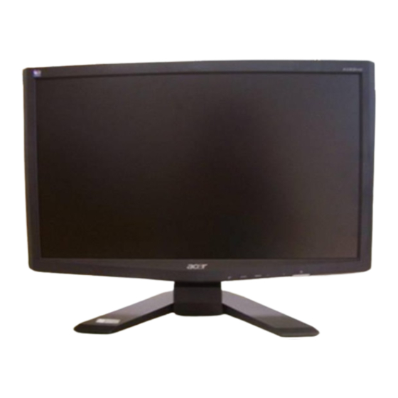
Appendix 2 – Physical Dimension Front View and Side view Fig. 1 Appearance Description - 70 -... -
Page 72: Appendix 3 - Led Driver
Appendix 3 – LED Driver - 71 -... -
Page 73: Appendix 4 -Power Board
Appendix 4 –Power Board - 72 -... -
Page 74: Appendix 5 -Interface Board
Appendix 5 –Interface Board Please see next page - 73 -... - Page 75 +3.3V D N2 D N3 0 .1 U K 0 .1 U K 0 .1 U K BAV99 BAV99 BAV99 D N5 +3.3V PC5V BAV70LT1G +3.3V DVIPC5V EDID_ VCC D N6 BAV70LT1G all 100 PC5V 75 J 75 J 75 J 4 .7 P C 4 .7 P C 4.7P C...
- Page 76 R 1 .8DVCC RM2101B0DA +3.3V T MDS_VDD C 36 1 U K 1K J 47U 25V 0.1U K 0.1U K 0.1U K giachin 2525L (0719) RXO1- V1/REXT TXO1- RXO1- RX1P RXO1+ RX1P V2/RX1P TXO1+ RXO1+ RX1N RXO2- RX1M RXO2- V3/RX1N TXO2- BJT 3906 change to BJT2907 RX0P...
- Page 77 2K61185110 0.1U K 22U 25V 0.1U K 0.1U K 0.1U K 0.1U K 0.1U K 2KK2087007 4.7K J +3.3V POWER_KEY Acer Ctrl_BD LED(Blue): R 47 2N3906S LED_ORG LED_ORG 1K J 2N3906S LED_GRN LED_GRN 10K J R105 2K J AD C_KEY1...
- Page 78 2525L (0719) giachin 2525L (0824) I-KEY R301 BL_ON +3.3V +3.3V NVRAM 4.7K J C 62 Acer Ctrl_BD LED(Blue): 0.1U K R30 0 J R31 0 J VOL_ADJ R 28 4.7K J +3.3V +3.3V C101 0.1U 4.7K J 4.7K J...
- Page 79 U9 spec. Vds=-30V, Vgs=+/-12V Id=-3.5A when ambient temp.=70 degre LCD_5V_POWER 100K J G(1) D(3) R222 150 J S(2) 22U 25V 0.1U K AO3401L cost down 22uF 150 ohm and 1206 size PANEL_ON 2N3904S 22U 25V 10K J cost down 22uF 0.1U K Screw Holes Add wireharness connector for improving EMI issue.
Need help?
Do you have a question about the X193HQL and is the answer not in the manual?
Questions and answers