Table of Contents
Advertisement
Quick Links
Advertisement
Table of Contents

Related Manuals for Duratech DLM-450


Summary of Contents for Duratech DLM-450
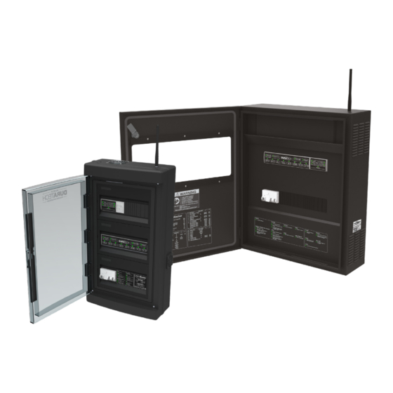
- Page 1 Manual DLM-450 & DLM-600 LINK Master...
-
Page 2: Table Of Contents
2.2.8.1. Schedules 2.2.8.1.1 Schedules overview 2.2.8.1.2. Create schedules 2.2.8.1.3. Schedule detail 2.2.8.2. Schedule events 2.2.8.2.1. Creating events 2.2.8.2.3. Deleting events 2.2.8.2. Duratech Schedules 2.3. Operation 2.3.1. Keypad operation 2.3.1.1. Controller keypad 2.3.1.2. Gateway keypad 2.3.2. Discovery/Pairing mode 2.3.3. Automatic mode 2.3.4. - Page 3 2.3.7. Error codes 2.4. Updating 2.4.1. Controller 2.4.2. Gateway 2.5. Safety Conditions 3. Pool light 3.1. Installation 3.1.1. Wiring instructions 3.2. Configuration 3.2.1. Lamp type selection 3.2.2. Pool light synchronisation 3.2.3. Manual pool light synchronization 3.3. Operation 3.3.1. LinkTouch 3.3.1.1. Control functions 3.3.1.2.
- Page 4 5.4. Updating 5.5. Safety conditions 6. Cover 6.1. Installation 6.1.1. DURACOVER Cover System wiring instructions 6.1.2. Multi-Brand Cover wiring instructions 6.1.3. Key Switch installation 6.2. Configuration 6.2.1. DURACOVER Cover System 6.2.1.1. Pairing 6.2.1.2. Calibrating 6.2.1.3. Configuration of the Dead Man Switch (DMS) 6.2.2.
-
Page 7: Introduction
1. Introduction 1.1. About the LINK Master Thank you for purchasing this House of DURATECH product. To ensure proper operation, please read this manual carefully before using the device. After reading this manual, be sure to keep it for future reference. -
Page 8: Box Content
Check that the following parts are supplied with the product. 1 x Cabinet 1 x Wall mounting plate (only DLM-600) 2 x Cabinet door triangle keys (only DLM-600) 1 x Quick guide 1 x Fixing set (screws, plugs) 1 x Antenna DLM-450 DLM-600... -
Page 9: Keypad
1.3. Keypad High level overview of the LINK Master and the two keypads that are inside. DLM-450 DLM-600... -
Page 10: Controller Keypad
1.3.1. Controller keypad Manual button Filling button Aux button Cover button Used for switching between Used for enabling/disabling Used for turning Auxiliary port This button will open/close manual and automatic mode. the filling mode of the pool. on or off. the pool cover DuraLink button Heating button... -
Page 11: Link Master
The antenna needs to be attached on the top right of the LINK Master The LINK Master cabinet needs to be mounted vertically and permanently on a solid wall with sufficient bearing capacity. Respect a free space around the LINK Master cabinet for unobstructed airflow. (see drawing below) DLM-450 DLM-600... -
Page 12: Provisions
The location where the LINK Master will be installed must be protected from dust and water in order to ensure that the device functions properly. The ambient temperature must be between 0°C and +40°C and must be as constant as possible. The relative humidity at the location of installation must not exceed 90%, no condensation may occur. -
Page 13: Phyisical Installation
2.1.1.3. Phyisical installation DLM-450 installation DLM-450 Using the screws the DLM-450 can be installed securely. DLM-600 DLM-600 installation 1. Fix the wall mounting plate to the wall using the included (plugs) and screws. 2. Lift the Link Master up, and position in front of the hooks on the mounting plate. (best with 2 persons) 3. -
Page 14: Electrical Installation
2.1.2. Electrical installation High level overview of the DLM-450 and the parts that are inside. DLM-450 overview Antenna Transformer Gateway Controller Circuit Terminal breakers Blocks DLM-450 terminal blocks... - Page 15 High level overview of the DLM-600 and the parts that are inside. DLM-600 overview Antenna Transformer Controller Gateway Circuit breakers Terminal Blocks DLM-600 terminal blocks...
-
Page 16: Wiring Instructions
Connect the 230VAC power supply cable Ensure the correct connection of the grounding (terminal 1) The load of the DLM-450 may not exceed 350VA. The load of the DLM-600 may not exceed 500VA. DLM-450 inside cabinet sticker Description... - Page 17 DLM-600 inside cabinet sticker...
-
Page 18: Network Installation
For the DuraCloud App to communicate with the LINK Master it needs to be connected to a ‘router’ device providing wireless (cloud) access. This access is essential to be able to fully configure your LINK Master (→ 2.2) The ‘router’ device cable should be connected in the LAN socket. (drawings below) DLM-450 DLM-600 ROUTER... -
Page 19: Dmx Controller Installation
The DMX controller can be connected to the LINK Master in the following way. Connect the DMX controller wires to the connection terminal blocks - 17 and 18 on the DLM-450 - 24 and 25 on the DLM-600 For more information about how to use the DMX commands please refer to (→ 3.3.5.) -
Page 20: Rs485 Controller Installation
Connect the RS485 controller wires to the connection terminal blocks - 15 and 16 on the DLM-450 - 20 and 21 on the DLM-600 For more information about how to use the RS485 commands please refer to (→ 4.3.3.) -
Page 21: Configuration
2.2. Configuration 2.2.1. System start-up For the initial start-up the LINK Master Controller and Gateway keypads will be used be- cause the DuraCloud App and LINK Touch are not yet paired with the LINK Master. Also be aware that the last step in the initial start-up of the Gateway is to search for any software updates. - Page 22 network as the LINK Master. Open the DuraCloud App on your ‘smart’ device. Open the menu on the top left Navigate to “Claim Ownership” Select the Gateway keypad button “Owner” to obtain authorised access. Click on the gateway in the DuraCloud App you want to promote When the DuraCloud App shows that it has become owner, the procedure has successfully been completed.
-
Page 23: Configure Other Devices
2.2.3. Configure other devices Before continuing with the pairing of the LINK Touch (→ 2.2.6.) it is important that all installed devices are correctly paired with the LINK Master. Pool lights (→ 3.2.) Heat pump (→ 4.2.) Filter pump (→ 5.2.) 2.2.4. -
Page 24: Configure Input C As Level Sensor
(<2m) of the LINK Master. After completing this pairing sequence the LINK Touch will be able to ‘wirelessly’ operate the installed House of DURATECH devices (Heat pump, Pool lights and Cover) or similar multi-brand components (limited functions). Steps for pairing: Press the DuraLink button on your controller keypad. - Page 25 Steps on LINK Touch for pairing: Click the screen once on your LINK Touch display Hold the screen for 3 seconds to open the settings menu. Touch the screen once to put the LINK SETTINGS Touch in pairing mode. Pair start The LINK Touch will now start the pairing with the LINK Master When the pairing is successfully completed, the LINK Touch display will show “DLMXXX Paired”...
-
Page 26: Configuring Smart Rules
2.2.7. Configuring smart rules Smart rules are pre-programmed to automate processes of specific pool devices con- nected with the LINK Master. The only manual options remaining are to select, activate and to deactivate the ‘Smart Rules’. Manual selections for ‘Smart Rules’ between two devices. Filter pump <>... - Page 27 - Filter pump runs regularly for a short time to support measuring of the temperature. (Only for DURAHEAT) → The DURAHEAT heat pump has a temperature sensor that is used to measure the temperature of the pool. However, when there has been no flow through the tubes for some time, the temperature in the tubes can vary significantly from the actual pool tem- perature.
-
Page 28: Scheduler
DuraCloud App. 2.2.8.1. Schedules By default, there are 4 ‘Duratech schedules’ available. These preset schedules are opti- mally tailored to ensure the automatic working of the different pool devices is in line with the selected ‘mode’. When more customization is needed, new ‘Custom Schedules’ can be made using the DuraCloud App. -
Page 29: Schedules Overview
1. Open the DuraCloud App and navigate to the relevant pool. 2. Click the clock icon ‘ ’ in the top right of the DuraCloud App screen. 3. This page will show all the ‘Duratech schedules’ and ‘Custom schedules’ 2.2.8.1.2. Create schedules To create a ‘Custom schedule’:... -
Page 30: Schedule Detail
2.2.8.1.3. Schedule detail Viewing the schedule details can be done by selecting the schedule in the overview. After opening the schedule, it can be deleted or activated. To activate the schedule, click the ‘Run’ icon in the top right of the DuraCloud App screen. -
Page 31: Schedule Events
2.2.8.2. Schedule events Every schedule consists of multiple events. These events can be set for filter pump, heat pump and pool lights. These events can be created, updated, and deleted via the Dura- Cloud App. 2.2.8.2.1. Creating events When creating a schedule there is the option to add events to these schedules using the ‘+’... -
Page 32: Deleting Events
When creating a schedule there is the option to delete events, to do this hold the event and you get the option to delete the event. 2.2.8.2. Duratech Schedules These are our different duratech schedules: - High - Normal - on/off... - Page 33 - High → Everything running at full power - Normal → Everyday use, the controller keeps the pool as clean and warm as possible with the least amount of energy. NORMAL ON/OFF...
- Page 34 NORMAL MULTI-BRAND INVERTER NORMAL INVERTER...
- Page 35 - Eco → Everything is running at a bare minimal to keep the pool clean and warm. No automatic systems are allowed to work outside the scheduled times. ECO ON/OFF ECO MULTI-BRAND INVERTER...
- Page 36 ECO INVERTER - Off → Everything is off...
-
Page 37: Operation
2.3. Operation When the configuration has been completed the LINK Master is ready for daily use. The LINK Master will standard and therefore in most cases be running in the automatic mode. • Automatic mode (→ 2.3.3.) Additional operation modes & informations are available and explained in the following chapters. -
Page 38: Gateway Keypad
2.3.1.2. Gateway keypad On/Off button Cloud LED This led will be on if your This button will turn on/off the LINK Master has an internet gateway. connection. DuraLink LED Direct Wifi button This button will enable This led will blink if it receives an access point on your a wireless DuraLink message. -
Page 39: Discovery/Pairing Mode
2.3.2. Discovery/Pairing mode The Pairing/Discovery mode is used to connect House of DURATECH devices with the LINK Master. The LINK Master will be able to pair with all devices part of the DuraLink connected product range. Enabling pairing/discovery mode: This mode is enabled by pressing the Duralink button on the LINK Master controller key- pad. -
Page 40: Automatic Mode
2.3.3. Automatic mode By default the LINK Master is in Automatic mode. In this mode the LINK Master will follow the schedule which is behind the selected Pool mode. (→ 2.2.8.) Returning to Automatic mode • From Automatic mode with user override ( 2.3.4. ) the LINK Master can go to Auto- matic mode by pressing the MANUAL button on the keypad. -
Page 41: Automatic Mode With User Override (Service Mode)
2.3.4. Automatic mode with user override (service mode) The automatic mode with user override is used to give manual access to each individual device. The functioning of each device can be enabled or disabled manually with the Keypad buttons, LINK Touch or DuraCloud App. The automatic mode with user override can be activated in multiple ways. - Page 42 All other devices will continue to work as set. Using Filling in The automatic mode with user override. • Filling is only available when Relay B is configured as Filling output (→ 2.2.3.), if filling is activated without the correct configuration of Relay B, the led will blink 3 times fast. •...
-
Page 43: Cleaning Mode
2.3.5. Cleaning Mode The Cleaning mode allows you to do all the necessary cleaning jobs more easy and effi- cient. Without the interference of any automatic system on the pool. The Cleaning mode can be activated by pressing the button “Cleaning” on the Keypad. This mode can be used to allow the following tasks: •... -
Page 44: Direct Wifi
2.3.6. Direct Wifi Direct Wifi is used to provide a temporary hotspot to configure your pool when there is no connection available. By pressing the button ‘Direct Wifi’ on your gateway key- pad the hotspot will be enabled for 2 hours. This will allow you to configure and control your pool for this time period. -
Page 45: Error Codes
2.3.7. Error Codes The "Error Code" chapter of the LinkMaster controller manual is dedicated to helping you diagnose and troubleshoot any issues that may arise while using the controller. When an error occurs, all of the LEDs on the bottom row will start blinking and the top row of LEDs will indicate a binary error code. -
Page 46: Updating
Insert the SD-card containing the firmware update into the SD-card slot on the controller board (note: this step is only available for authorized House of DURATECH support staff) Turn on the LINK Master The controller will update, and the 8 bottom leds will display a wave animation... -
Page 47: Safety Conditions
2.5. Safety Conditions The LINK Master is fitted with several safety features. They can be split in two main cate- gories. - External - Differential switch 30mA - Circuit Breakers - Internal - Current measurement on all 12V & 24V outputs of the controller - Software safety for maximum currents - Automatic setting for maximum currents... -
Page 48: Pool Light
3. Pool light DuraVision offers four types of pool lights (model codes are listed) which can be con- nected to the LINK Master. Each type has their own functionality, with the PLC being fully compatible with all features available on the LINK Master. •... -
Page 49: Installation
‘Daisy Chain’ layout, for the best optimal performance with the LINK Master. Pool Pool Pool Pool house house Daisy chain connection Star connection The pool light wires are connected to the assigned vision block. Ensure the screws are firmly tightened! DLM-450 pool light wiring... - Page 50 DLM-600 pool light wiring...
-
Page 51: Configuration
3.2. Configuration The connected pool lights will automatically be selected by the LINK Master. However we highly recommend verifying the settings and when needed adjusting to the specific model pool light in the DuraCloud App. (→ 3.2.1.) 3.2.1. Lamp type selection Please follow the below sequence: Open the DuraCloud App and ensure it has the owner role for the relevant pool. -
Page 52: Pool Light Synchronisation
3.2.2. Pool light synchronisation This synchronisation option is not used for ON/OFF pool lights and PLC controlled pool lights Synchronization is only required for the toggle pool lights, to ensure that all pool lights are running the same color scene. This process of synchronising the scenes generally takes 45 seconds to complete. -
Page 53: Operation
3.3. Operation 3.3.1. LinkTouch The LINK Touch can be used to control the pool lights wirelessly, the LINK Touch provides the following functions: Turning pool lights On/Off Dimming of the pool lights (PLC pool lights only) Changing the color (only for RGB pool lights) Changing color scenes (predefined by DuraVision) Changing CCT (Correlated Color Temperature) for RGB and TW pool lights... -
Page 54: Control Functions
3.3.1.1. Control functions Corelated Colour temperature (CCT): Slide to the right to adjust the pool light from “warm white” to “cool white” ON/OFF Lights: Press to switch all Lights ON/OFF Colour wheel: Slide to change colour of Pool Lights (only DLT10-RGB) Colour program: Press for next colour program. -
Page 55: Advanced Control Functions
3.3.1.2. Advanced control functions Activate the settings menu, then use right arrow key to select the desired setting and the left arrow key to exit the setting. Activate the settings menu, then use right arrow key to select the desired setting Touch the display for 3 seconds to activate the settings menu. -
Page 56: App
3.3.2. App 3.3.3. DMX controller operation When using a DMX controller for operating the pool light, the functionalities of the LINK Touch or the DuraCloud App will no longer be active. 3.3.4. RS485 command set Function Command Remark Example Avail- Available able in PLC... - Page 57 Color temperature PTxyz x = ten thousand; y = thou- PT035 = Set white color sand; z = hundred temperature to 3500K (in steps of 500K)
-
Page 58: Updating
3.4. Updating Currently the DuraVision pool lights do not support remote updating. 3.5. Safety conditions Do not use DC voltages with the pool lights Ensure the voltage meets the required 12VAC (10-14 VAC) -
Page 59: Heat Pump
The maximal power supply is limited to 20A with a peak current of 25A. Connect- ing a three phase 400VAC is not supported. 4.1.1. DURAHEAT heat pump The designated connection terminal blocks need to be used to connect the ‘DURAHEAT’ heat pump to the LINK Master. DLM-450 heat pump wiring... - Page 60 DLM-600 heat pump wiring...
-
Page 61: Multi-Brand Heat Pump With Link Dongle
‘DURAHEAT’ heat pump and are wired in a similar way as the above ‘DURAHEAT’ heat pumps. The designated connection terminal blocks need to be used to connect the ‘DURAHEAT’ heat pump to the LINK Master. DLM-450 heat pump wiring DLM-600 heat pump wiring... -
Page 62: Multi-Brand Heat Pump Without Link Dongle
4.1.3. Multi-brand heat pump without LINK dongle Multi-brand heat pumps are not supported. They need to be installed and operated as a stand-alone device. Therefor the designated connection terminal blocks on the LINK Master cannot be used for the electrical connection. -
Page 63: Configuration
4.2. Configuration 4.2.1. Pairing the DURAHEAT heat pump Multi-brand heat pumps with the LINK Dongle will be recognized as a ‘DURAHEAT’ heat pump and are paired in a similar way as the ‘DURAHEAT’ heat pumps. For the ‘DURAHEAT’ heat pump to work correctly it needs to be paired with the LINK Master. -
Page 64: Operation
4.3. Operation 4.3.1. LINK Touch The LINK Touch can be used to control the ‘DURAHEAT’ heat pump wirelessly, the LINK Touch supports the following functions for controlling the ‘DURAHEAT’ heat pump: Turning the ‘DURAHEAT’ heat pump ON/OFF Changing the pool water setpoint temperature Displaying the actual pool water temperature Error feedback (‘DURAHEAT’... -
Page 65: Updating For 'Duraheat' Heat Pump
4.4 Updating for ‘DURAHEAT’ heat pump Multi-brand heat pumps with the LINK Dongle will be recognized as a ‘DURAHEAT’ heat pump and the LINK Dongle is updated in a similar way as the ‘DURAHEAT’ heat pumps. The gateway will automatically update the ‘DuraHeat’ heatpumps when connected to the internet and when a new firmware version is available. -
Page 66: Safety Conditions
4.5. Safety conditions Please refer to the ‘DURAHEAT’ heat pump manual for specific safety conditions. For the LINK Master, do not exceed the ‘DURAHEAT’ power supply values mentioned in the installation chapter. (→ 4.1.) -
Page 67: Filter Pump
Ensure the advised cable sections are adhered to when connecting the DURAFLOW Variable Speed filter pump. The designated connection terminal blocks need to be used to connect the DURAFLOW Variable Speed filter pump to the LINK Master. Ensure the screws are firmly tightened! DLM-450 filter pump wiring... - Page 68 DLM-600 filter pump wiring...
-
Page 69: Multi-Brand Single Speed Filter Pump Wiring Instructions
Ensure the advised cable sections are adhered to when connecting the Multi-Brand Sin- gle Speed filter pump. The designated connection terminal blocks need to be used to connect the Multi-Brand Single Speed filter pump to the LINK Master. Ensure the screws are firmly tightened! DLM-450 filter pump wiring DLM-600 filter pump wiring... -
Page 70: Multi-Brand Variable Speed Filter Pump Wiring Instructions
For example; using Relay A for the Multi-Brand Variable Speed filter pump, restricts also using the LINK Master for the connection of a Multi-Brand cover. They cannot be combined. DLM-450 filter pump wiring with boost cable... - Page 71 DLM-600 filter pump wiring with boost cable...
-
Page 72: Configuration
5.2. Configuration 5.2.1. Pairing the DURAFLOW Variable Speed filter pump For the ‘DURAFLOW’ Variable Speed filter pump to work correct it needs to be paired with the LINK Master. Be aware that the LINK Touch and DuraCloud App require that the ‘DURAFLOW’... -
Page 73: Multi-Brand Single Speed Filter Pump
5.2.2. Multi-Brand Single Speed filter pump The Multi-Brand Single Speed filter pump does not require a dedicated pairing with the LINK Master. (For installation see 5.1.2.) However, the use of a Multi-Brand Single Speed filter pump does require the filter pump mode to be correctly configured in the DuraCloud App. -
Page 74: Operation
5.3. Operation The filter pump is the core device for a swimming pool set up. It provides the water flow needed for most of the other devices to make them work. Therefor the filter pump’s operation is fully managed by the LINK Master, however there are settings that can be changed to optimize your filter pump. -
Page 75: Multi-Brand Single Speed Filter Pump
Skimmer Function - This function increases the speed of the filter pump periodically, making sure that the dirt floating on the water surface of the pool gets pushed to the skimmer in an efficient and fast way. The Skimmer Function duration and -interval can be adjusted in the DuraCloud App. -
Page 76: Updating
5.4. Updating The gateway will automatically update the ‘DURAFLOW’ inverter filter pump when con- nected to the internet and when a new firmware version is available. -
Page 77: Safety Conditions
5.5. Safety conditions Please refer to the ‘DURAFLOW’ Variable Speed filter pump manual for specific safety conditions. Please refer to the Multi-Brand filter pump manual for specific safety conditions. -
Page 78: Cover
(→ 6.2.2.) 6.1.1. DURACOVER Cover System wiring instructions Ensure the advised cable sections (Cable B in picture …. ) are adhered to when connect- ing the DURACOVER Cover system. Control Box (DLM-450/DLM-600) Connection Box in Cable Well Water Level Tubular Motor... - Page 79 The designated connection terminal blocks need to be used to connect the ‘DURACOV- ER’ Cover System to the LINK Master. DLM-450 cover wiring DLM-600 cover wiring...
-
Page 80: Multi-Brand Cover Wiring Instructions
LINK Master over the Relay A and B to the stand alone Multi-Brand controller. The LINK Master is ‘sort of’ in the middle of the Multi-Brand cover. This information is important for the LINK Master to make the Smart Rules work correctly. DLM-450 Multi-Brand Cover wiring DLM-600 Multi-Brand Cover wiring... -
Page 81: Key Switch Installation
Switch. The designated connection terminal blocks need to be used to connect the Key Switch to the LINK Master. DLM-450 • The lead wires of the key-switch must be connected to Terminal blocks 21 - Closing the contact will OPEN the cover... -
Page 82: Configuration
6.2. Configuration 6.2.1. DURACOVER Cover System 6.2.1.1. Pairing The DURACOVER Cover System does not require a dedicated pairing with the LINK Mas- ter. It is already part of the LINK Touch pairing sequence with the LINK Master. 6.2.1.2. Calibrating Calibration of a DURACOVER Cover System is required to have the cover moving to the open and close position correctly. -
Page 83: Configuration Of The Dead Man Switch (Dms)
6.2.1.3. Configuration of the Dead Man Switch (DMS) One essential configuration is the setting of the Dead Man Switch (DMS). This is a safety feature to prevent dangerous and harmful situations when using the cover. Preventive measure. Always ensure there is a visual contact with the pool when operating the cover. -
Page 84: Multi-Brand Cover
6.2.2. Multi-Brand Cover Multi-brand covers, using their own stand-alone cover controller can be controlled via relays A and B on the LINK Master. In this case the two relays A and B of the LINK Master will drive the stand-alone cover controller and simulate a key contact (left/right rotation of the motor) For further calibration of the Multi-Brand cover and its positioning please refer to the man- ual of this specific device. -
Page 85: Operation
6.3. Operation 6.3.1. DURACOVER Cover System The full control for the DURACOVER Cover system is integrated in the LINK Master. 6.3.1.1. Controller keypad The LINK Master Controller keypad button ‘Cover’ can be used to operate the DURA- COVER Cover System. The pressing is organized in a cycle. -
Page 86: Link Touch
6.3.1.2. LINK Touch The Open and Close cover buttons on the LINK Touch can be used to operate the DURA- COVER Cover System. The touching of the ‘Cover Open’ symbol on the LINK Touch screen will open the cover. The touching of the ‘Cover Close’ symbol on the LINK Touch screen will close the cover. Pool cover OPEN: Press or hold to open the pool cover depending on your DMS configuration. - Page 87 When the DeadManSwitch (DMS) is enabled the ‘Cover Open’ or ‘Cover Close’ symbol on the LINK Touch screen must be kept touched to activate the function. When the DeadManSwitch (DMS) is disabled the ‘Cover Open’ or ‘Cover Close’ symbol on the LINK Touch be released after touching. The opening and closing functions will work until the calibrated end positions of the cover.
-
Page 88: Duracloud App
6.3.1.3. DURACloud App The Open and Close cover buttons on the DuraCloud App can be used to operate the DURACOVER Cover System. The touching of the ‘Cover Open’ symbol on the DuraCloud App will open the cover. The touching of the ‘Cover Close’ symbol on the DuraCloud App will close the cover. In case the cover is already open and the user presses the “Open”... -
Page 89: Key Switch
6.3.1.4. Key Switch The Open and Close cover positions on the Key Switch can be used to operate the DURACOVER Cover System. Turning the key to the ‘Cover Open’ position on the Key Switch will open the cover. Turning the key to the ‘Cover Close’ position on the Key Switch will close the cover. When the DeadManSwitch (DMS) is enabled the key must be kept turned into the ‘Cover Open’... -
Page 90: Controller Keypad
6.3.2. Multi-brand Cover 6.3.2.1. Controller keypad The LINK Master Controller keypad buttons ‘Relay A’ and ‘Relay B’ can be used to oper- ate the Multi-brand Cover. By pressing the ‘Relay A’ button you will open your Multi-brand cover. By pressing the ‘Relay B’ button you will close your Multi-brand cover 6.3.2.2. -
Page 91: Duracloud App
6.3.2.3. DURACloud App The Open and Close cover buttons on the DuraCloud App can be used to operate the Multi-Brand cover. The touching of the ‘Cover Open’ symbol on the DuraCloud App will open the cover. The touching of the ‘Cover Close’ symbol on the DuraCloud App will close the cover. When the Multi-Brand cover is opening or closing, the feedback of the actual position will not be pictured as a live animation in the DuraCloud App. -
Page 92: Updating
6.4. Updating The LINK Master Gateway is updated automatically after House of DURATECH releases a new firmware version. The DURACOVER Cover System functions are part of the LINK Master updates and distributed to the LINK Touch. -
Page 93: Safety Conditions
6.5. Safety conditions Please refer to the ‘DURACOVER’ Cover system for specific safety conditions. When selecting the spot for fitting the key switch, make sure there will be an unobstructed line-of-sight with the pool when using the key switch. This way, the user can intervene immediately in case of any problems. -
Page 94: Duracloud
DuraCloud App will also be accessible through our web portal The DuraCloud App is available from the Google Play store and the Apple App Store by searching “DuraCloud”, you can also find a redirect on our website (https://duratech.be). 7.2. Configuration When starting the DuraCloud App it needs to be connected to a selected pool to start the configuration. -
Page 95: Features
7.3.3. Remote support By using the DuraCloud platform, remote support can be provided for the LINK Master and the House of Duratech connected devices. If any issues occur please first ready the related chapter for the initial problem solving of the connected device. - Page 96 Propulsion Systems bvba Dooren 72 1785 Merchtem, Belgium Tel +32 2 461 02 53 Fax +32 2 706 59 60 www.duratech.be info@propulsionsystems.be We reserve the rights to change all or part of the contents of this document without prior notice...
Need help?
Do you have a question about the DLM-450 and is the answer not in the manual?
Questions and answers