Table of Contents
Advertisement
Quick Links
Advertisement
Table of Contents

Related Manuals for Duratech DLM-600


Summary of Contents for Duratech DLM-600
- Page 1 Manual DLM-600 LINK Master...
-
Page 2: Table Of Contents
Contents 3.3.1.1. Control functions 1. Intro duction 3.3.1.2. Advanced control functions 1.1. About the LINK Master 3.3.2. App 1.2. Box-content 3.3.3. DMX controller operation 1.3. Keypad 3.3.4. RS485 command set 1.3.1. Controller keypad 3.4. Updating 1.3.2. Gateway keypad 3.5. Safety conditions 2. - Page 3 6.3.1.4. Key Switch 6.3.2. Multi-Brand Cover 6.3.2.1. Keypad 6.3.2.2. LINK Touch 6.3.2.3. DURACloud App 6.3.2.4. Key Switch 6.4. Updating 6.5. Safety conditions 7. DuraCloud 7.1. Installation 7.2. Configuration 7.3. Operation 7.3.1. Accessibility 7.3.2. Features 7.4. Updating...
-
Page 4: Intro Duction
1. Intro duction 1.1. About the LINK Master Thank you for purchasing this House of DURATECH product. To ensure proper operation, please read this manual carefully before using the device. After reading this manual, be sure to keep it for future reference. -
Page 5: Box-Content
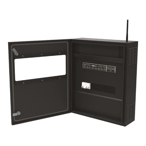
High level overview of the LINK Master and the two keypads that are inside. Check that the following parts are supplied with the product. 1 x Cabinet 1 x Wall mounting plate 2 x Cabinet door triangle keys 1 x Quick guide DLM-600 1 x Fixing set (screws, plugs) 1 x Antenna DLM-600... -
Page 6: Controller Keypad
DuraLink button Heating button Sensors button Relay A button DLM-600 Used for turning the sensors Used for activating your Used for enabling/disabling Used for turning the heat on or off. Relay A function. (→... -
Page 7: Provisions
2.1.1.3. Phyisical installation protected from dust and water in order to ensure that the device functions properly. DLM-600 The ambient temperature must be between 0°C and +40°C and must be as constant as possible. The relative humidity at the location of installation must not exceed 90%, no condensation may occur. -
Page 8: Electrical Installation
Connect the 230VAC power supply cable Ensure the correct connection of the grounding (terminal 1) Transformer Gateway Controller The DLM-600 may not not exceed 500VA and the current 42A DLM-600 inside cabinet sticker Circuit breakers Terminal Blocks... -
Page 9: Network Installation
Connect the DMX controller wires to the connection terminal blocks The ‘router’ device cable should be connected in the LAN socket. (drawing 29 and 30 on the DLM-600 below) For more information about how to use the DMX commands please refer to (→... -
Page 10: Configuration
2.2. Configuration 2.2.2.2. DuraCloud - owner of the pool The DuraCloud App will give access to all options available for the configu- 2.2.1. System start-up ration of the pool in a smart and simple way. For the initial start-up the LINK Master Controller and Gateway keypads will be used because the DuraCloud App and LINK Touch are not yet paired with Next is for the DuraCloud App to obtain the ‘Owner role’... -
Page 11: Configuring Other Devices
After completing this pairing sequence the LINK Touch will be able to ‘wire- You can now change relays A & B to the preferred mode. lessly’ operate the installed House of DURATECH devices (Heat pump, Pool Relay A lights and Cover) or similar multi-brand components (limited functions). -
Page 12: Configuring Smart Rules
Steps on LINK Touch for pairing: Warmup Click on this pair screen once on your LINK Touch display – Once the heat pump has been deactivated, the heatpump will still run about 15 minutes till full stop, to avoid damage to the internal circuit of the heat pump –... - Page 13 Normal NORMAL INVERTER → Everyday use, the controller keeps the pool as clean and warm as possible with the least amount of energy. NORMAL ON/OFF → Everything is running at a bare minimal to keep the pool clean and warm. No automatic systems are allowed to work outside the scheduled times.
-
Page 14: Operation
ECO MULTI-BRAND INVERTER 2.3. Operation When the configuration has been completed the LINK Master is ready for daily use. The LINK Master will standard and therefore in most cases be run- ning in the automatic mode. • Automatic mode (→ 2.3.3.) Additional operation modes &... -
Page 15: Gateway Keypad
2.3.1.2. Gateway keypad 2.3.2. Discovery/Pairing mode The Pairing/Discovery mode is used to connect House of DURATECH devic- es with the LINK Master. The LINK Master will be able to pair with all devices part of the DuraLink connected product range. -
Page 16: Automatic Mode
2.3.3. Automatic mode 2.3.4. Manual mode (service mode) By default the LINK Master is in Automatic mode. In this mode the LINK The Manual mode (service mode) is used to give manual access to each Master will follow the schedule which is behind the selected Pool mode. individual device. -
Page 17: Updating
(LINK Master only) is inserted in the SD-card slot on the controller board. (only available for authorized House of DURATECH support staff ) Update procedure: Turn OFF the LINK Master Insert µSD Card... -
Page 18: Safety Conditions
3. Pool light 2.5. Safety Conditions The LINK Master is fitted with several safety features. They can be split in DuraVision offers four types of pool lights (model codes are listed) which two main categories. can be connected to the LINK Master. Each type has their own functionality, External with the PLC being fully compatible with all features available on the LINK Differential switch 30mA... -
Page 19: Installation
The pool light wires are connected to the assigned vision block. Ensure the PLP WH screws are firmly tightened! PLP TW PLP WW DLM-600 pool light wiring PLP BL PLP RGB DVP RGBW When using Multi-Brand pool lights, the lamp needs to be selected from one of the corresponding type of pool lights. -
Page 20: Pool Light Synchronisation
3.2.2. Pool light synchronisation 3.3. Operation 3.3.1. LinkTouch This synchronisation option is not used for ON/OFF pool lights and The LINK Touch can be used to control the pool lights wirelessly, the LINK PLC controlled pool lights Touch provides the following functions: Turning pool lights On/Off Dimming of the pool lights (PLC pool lights only) Changing the color (only for RGB pool lights) -
Page 21: Control Functions
3.3.1.1. Control functions 3.3.1.2. Advanced control functions Activate the settings menu, then use right arrow key to select the Corelated Colour temperature (CCT): desired setting and the left arrow key to Slide to the right to adjust the pool light exit the setting. -
Page 22: App
3.3.2. App Set color in hex Pcrgbe Variable size, rgb = ASCII Pc64128255e = Red 25%, 0-255, e = end character Green 50%, Blue 100% 3.3.3. DMX controller operation ON/OFF relay RPMx x = 1 (ON), 0 (OFF) PRM1 = Relay ON/OFF control When using a DMX controller for operating the pool light, the functionalities control of the LINK Touch or the DuraCloud App will no longer be active. -
Page 23: Updating
230VAC heat pump. The maximal power supply is limited to 20A with a peak current of 25A. Connecting a three phase 400VAC is not supported. 4.1.1. DURAHEAT heat pump The designated connection terminal blocks need to be used to connect the ‘DURAHEAT’ heat pump to the LINK Master. DLM-600 heat pump wiring... -
Page 24: Multi-Brand Heat Pump Without Link Dongle
For the ‘DURAHEAT’ heat pump to work correctly it needs to be paired with the LINK Master. Be aware that the LINK Touch and DuraCloud App require DLM-600 heat pump wiring that the ‘DURAHEAT’ heat pump is paired first. Please follow the sequence below to pair the ‘DURAHEAT’ heat pump. -
Page 25: Operation
4.3. Operation 4.4 Updating for ‘DURAHEAT’ heat pump Multi-brand heat pumps with the LINK Dongle will be recognized as a ‘DU- 4.3.1. LINK Touch RAHEAT’ heat pump and the LINK Dongle is updated in a similar way as the The LINK Touch can be used to control the ‘DURAHEAT’ heat pump wire- ‘DURAHEAT’... -
Page 26: Safety Conditions
Ensure the advised cable sections are adhered to when connecting the DU- RAFLOW Inverter filter pump. The designated connection terminal blocks need to be used to connect the DURAFLOW Inverter filter pump to the LINK Master. Ensure the screws are firmly tightened! DLM-600 filter pump wiring... -
Page 27: Multi-Brand On/Off Filter Pump Wiring Instructions
The designated connection terminal blocks need to be used to connect the Multi-Brand ON/OFF filter pump to the LINK Master. Ensure the screws are firmly tightened! DLM-600 filter pump wiring with boost cable DLM-600 filter pump wiring 5.1.3. Multi-Brand Inverter filter pump wiring instructions Ensure the advised cable sections are adhered to when connecting the Multi-Brand Inverter filter pump. - Page 28 5.2. Configuration 5.2.2. Multi-Brand ON/OFF filter pump The Multi-Brand ON/OFF filter pump does not require a dedicated pairing 5.2.1. Pairing the DURAFLOW Inverter filter pump with the LINK Master. It is already part of the LINK Touch pairing sequence For the ‘DURAFLOW’ Inverter filter pump to work correct it needs to be with the LINK Master.
-
Page 29: Operation
5.3. Operation 5.4. Updating The filter pump is the core device for a swimming pool set up. It provides The gateway will automatically update the ‘DURAFLOW’ inverter filter pump the water flow needed for most of the other devices to make them work. when connected to the internet and when a new firmware version is avail- Therefor the filter pump’s operation is fully managed by the LINK Master, no able. -
Page 30: Safety Conditions
(→ 6.2.2.) 6.1.1. DURACOVER Cover System wiring instructions Ensure the advised cable sections (Cable B in picture …. ) are adhered to when connecting the DURACOVER Cover system. Control Box (DLM-450/DLM-600) Connection Box in Cable Well Water Level Tubular Motor... -
Page 31: Key Switch Installation
Terminal blocks 25 and 26 - Closing the contact will CLOSE the cover DLM-600 Key Switch wiring 6.1.2. Multi-Brand Cover wiring instructions A Multi-Brand cover is supported by simulating the open and close Key- Switch functions with use of the Relay A and B terminals on the LINK Master. -
Page 32: Configuration
6.2. Configuration 6.2.1.3. Configuration of the Dead Man Switch (DMS) One essential configuration is the setting of the Dead Man Switch (DMS). 6.2.1. DURACOVER Cover System This is a safety feature to prevent dangerous and harmful situations when 6.2.1.1. Pairing using the cover. -
Page 33: Multi-Brand Cover
Please follow the below sequence when using the DuraCloud App: 6.2.2.2. Calibrating Open the DuraCloud App For further calibration of the Multi-Brand cover and its positioning please Make sure you are owner of the pool (2.2.2.2.) refer to the manual of this specific device. Click on the pool you wish to configure Click on the settings icon on the top-right of the DuraCloud App Look for “DeadManSwitch mode”... -
Page 34: Link Touch
6.3.1.2. LINK Touch When the DeadManSwitch (DMS) is enabled the ‘Cover Open’ or ‘Cover Close’ symbol on the LINK Touch screen must be kept touched to activate The Open and Close cover buttons on the LINK Touch can be used to oper- the function. -
Page 35: Duracloud App
6.3.1.3. DURACloud App 6.3.1.4. Key Switch The Open and Close cover buttons on the DuraCloud App can be used to The Open and Close cover positions on the Key Switch can be used to op- operate the DURACOVER Cover System. erate the DURACOVER Cover System. -
Page 36: Multi-Brand Cover
6.3.2. Multi-brand Cover 6.3.2.3. DURACloud App The Open and Close cover buttons on the DuraCloud App can be used to 6.3.2.1. Controller keypad operate the Multi-Brand cover. The LINK Master Controller keypad buttons ‘Relay A’ and ‘Relay B’ can be used to operate the Multi-brand Cover. -
Page 37: Key Switch
The LINK Master Gateway is updated automatically after erate the Multi-Brand cover. House of DURATECH releases a new firmware version. Turning the key to the ‘Cover Open’ position on the Key Switch will open The DURACOVER Cover System functions are part of the LINK Master up- the cover. -
Page 38: Safety Conditions
The DuraCloud App is available from the Google Play store and the Apple any problems. App Store by searching “DuraCloud”, you can also find a redirect on our website (https://DURATECH.be). 7.2. Configuration When starting the DuraCloud App it needs to be connected to a selected pool to start the configuration. -
Page 39: Features
7.3.3. Remote support By using the DuraCloud platform, remote support can be provided for the www.DURATECH.be LINK Master and the House of Duratech connected devices. info@propulsionsystems.be If any issues occur please first ready the related chapter for the initial prob- lem solving of the connected device.
Need help?
Do you have a question about the DLM-600 and is the answer not in the manual?
Questions and answers