Advertisement
Quick Links
INSTRUCTION
MANUAL
General
Description
Theory of
Operation
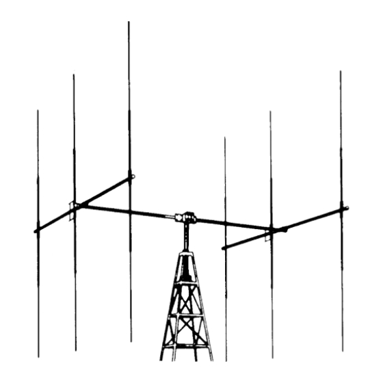
The Hy-Gain Model SDB6 is a twin-driven antenna system that mUltiples the effective
radiated power of any efficient 5-watt CB transceiver to 93 watts. The antenna system
consists of two 3-element beams stacked and connected with a phasing harness to obtain
maximum gain and directivity. It can be rotated with any heavy-duty rotator.
Taper-swaged,
seamless, aluminum tubing gives maximum mechanical strength and
durability. The compression clamps used at the tubing joints will not vibrate loose in the
wind. All hardware is iridite treated to prevent rust and corrosion. The Model SDB6 is built
to give years of trouble free service.
The Model SDB6 consists of two antennas, each with a reflector, driVen element and
director. The antennas are optimum spaced and fed with a pre-assembled
harness. This enables the signal from one antenna to reinforce the signal from the other
antenna. The overall effect is a tremendous gain in effective radiated power and maximum
front-to-back
ratio.
ORDER NO. 542
Model SDB6
"Super Duo-Beam" antenna
phasing
Advertisement

Related Manuals for Hy-Gain Super Duo-Beam


Summary of Contents for Hy-Gain Super Duo-Beam
- Page 1 MANUAL "Super Duo-Beam" antenna General The Hy-Gain Model SDB6 is a twin-driven antenna system that mUltiples the effective Description radiated power of any efficient 5-watt CB transceiver to 93 watts. The antenna system consists of two 3-element beams stacked and connected with a phasing harness to obtain maximum gain and directivity.
- Page 2 Gain 12.7 dB Front-to-back ratio 23 dB SWR at resonance less than 1.4:1 Coaxial feedline 52 ohms Lightning protection DC ground Boom length 12' 2" Cross boom length Longest element 18' 6W' Boom diameter 11,4" Cross boom diameter 2" Ye" Element diameter (tapers) 7116"...
- Page 4 ( ) Assemble the elements as shown in Figure 3. It is recommended that the reflector be assembled first and spaced 2%" from the end of the boom. Assemble the driven element and director and space as shown in Figure 6. All dimensions are measured center to center.
- Page 5 / -t s:;. 00'" '''' __ 'iIl RA~ATED powER ~. 2 . DIREWON ,.0.F ------...0 .' ..SLOT IN PIPE ALIGNED WITH -- #10-1 RH BOLT l#10-1" RH BOLT CENTER OF CLAMP OPENING 10 SQUARE SQUARE NUT Compression When installing compression clamps. move the clamp to the end of the tubing with the joint of the clamp even with the slot in the tUbing.
- Page 6 CAUTION DO NOT TWIST PHASING L1NES- TOP PHASING LINE CENTER CONDUCTOR CONNECTS TO TOP DRIVEN ELEMENT AND TOP HOLE IN FEED POINT SULATOR- BOTTOM PHASING LINE CENTER CONDUCTOR ATTACHES BOTTOM DRIVEN ELEMENT AND BOTTOM HOLE IN FEED POINT INSULATOR.
- Page 7 CHOKE FORMED BY 12 TURNS OF RG-S/U s" COAXIAL CABLE WOUND INCIRCLE WITH INSIDE DIAMETER TAPE TO MAST. FOR INCREASED EFFICIENCY. IT IS RECOMMENDED THAT YOU OBTAIN A HY-GAIN BALUN (CBl TO USE IN PLACE OF THE RF CHOKE. FEEDLINE FROM TRANSCEIVER (RG-S/U) 23/ 8 "...
- Page 8 Attach the othercendof the RF choke to the' transceiver: "' <:": ":,~::,;.:,::"":_":.,:,, , ", :.f~ For optimum band pas~·§.rt~signal gain,itis nOJcomtnendedthat a Hy-Gain Model BN-27 A balun be used. ( ) Securely tape all exposed portions the coaxial braid to prevent it from shorting out ort the antenna.
- Page 9 The Duo-Beam concentrates the transmission of signal energy in one main direction and in the receive function is much more sensitive to signals in that same direction. What this means to you is shown in Figure 9. Since CB stations are usually liberally scattered in all directions, it is easy to see that the Duo-Beam with its narrow pattern can be rotated or oriented to maximize transmission to, and reception of, anyone station or group of stations with which we wish to communicate.
- Page 10 As a direct result of the directivity of the Duo-Beam, a tremendous amount of gain is produced. Gain, of course, means increased signal strength - both transmitting and receiving - in the "power path" of the antenna. Checking To check the gain, observe the S-meter reading or signal to background noise ratio of the Gain another CB station.
- Page 11 Do not return anything until requested to do so. No warranty card is furnished; you must supply the above information. This warranty does not cover transportation costs that may be incurred. Hy-Gain Electronics Corporation's sole liability is the remedy of any defect for the ninety-day Any returned items must have prior authorization.
Need help?
Do you have a question about the Super Duo-Beam and is the answer not in the manual?
Questions and answers