
Subscribe to Our Youtube Channel
Related Manuals for LOWES H21015


Summary of Contents for LOWES H21015
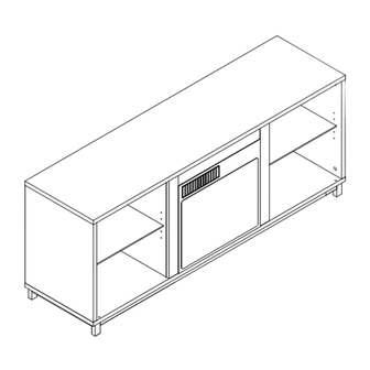
- Page 1 MANUAL INSTRUCTION TV Stand H21015 We offer a diverse range of products to meet the needs of customers.
- Page 2 Indoor Furniture We are a professional furniture provider with top-notch factories and outstanding designs, Ours mission is to provide consumers with new lifestyles By collecting consumer feedback,we constantly improve our products and create more choices for consumers. If you want to create your space, We are an ideal choice.
- Page 3 WARNING All the TV stands have passed strict quality inspections before delivery.Read this manual carefully to ensure proper usage...
- Page 4 WARNING Ensure that all parts and hardware are available before beginning assembly...
- Page 5 NOTICE NOTICE 1. Children are not allowed to operate. 2.Faster installation is possible with power tools. 3.Do not pull the door vigorously to prevent the storage cabinet from tipping over. 4.Please attach the storage cabinet to the wall with an anti-tip device after installation is complete.
-
Page 6: Tools Required
TOOLS REQUIRED Screwdriver 2-4 Persons Assembly Minimum 120 Minutes For Assembly PARTS 2PCS 2PCS... - Page 7 PARTS 2PCS 2PCS...
- Page 8 HARDWARE HARDWARE 8*30 mm 15*12 mm 6*43 mm 6PCS 22+1PCS 22+1PCS M6*12 mm M6*30 mm M6*40 mm 4+1PCS 10+1PCS 4+1PCS 8+1PCS 26PCS...
-
Page 9: Product Assembly
PRODUCT ASSEMBLY TV Stand 1.Use 4 bolt "F" secure part① to part③ with hex key "G" as per diagram 2.Use 4 bolt "D" to secure the middleof part③ and the both sides of part ②as per diagram. D x 4PCS F x 4PCS Using 10 bolt "E"secure the Installed part (①②③)to part⑤with hex key “G”... - Page 10 PRODUCT ASSEMBLY Turn the assembled parts in step 2 face up, and secure 8 cam bolt "c" into part⑤ with Philips head screwdriver as per diagram. Note:If the white plastic is not pressed into the C x 8PCS available tools can be gently knocked down Install 2 cam bolt "C"...
- Page 11 PRODUCT ASSEMBLY Connect part and part with 2 cam lock"B",and similarly connect part and part with 2 cam lock "B",locking the"B" clockwise. B x 4PCS...
- Page 12 PRODUCT ASSEMBLY Use 2 wooden dowel "A" to connect part &part with part . Two People cooperate,and then use 2 wooden dowel "A" to connect part &part with part Align the holes on the bottom of part &part with 4 camlock"C"above the part ,as per diagram.
- Page 13 PRODUCT ASSEMBLY 1.Align the holes on the bottom of the part &part with the 4 cam bolt "C"above the part as per diagram. 2.Put 4 cam lock"B"into the corresponding holes of part &part , and tighten cam lock"B"clockwise. NOTE:When installing.pay attention to distinguish between part and part ,part is on...
- Page 14 PRODUCT ASSEMBLY Screw 10 cam bolt "C" into part corresponding holes as per diagram. C x 10PCS Put Two "A" into the holes of part and part ,then put "4" into the corresponding position and lock it clockwise with 10"B",note that "13"should be stuck into the 4 slots.
- Page 15 PRODUCT ASSEMBLY 1.Put 8"H" into the corresponding holes. 2.Then put the glass laminate(part )into the cabinet. The cabinet installation is completed. H x 8PCS For beauty, you can cover the exposed holes with "I" according to your needs...
- Page 16 Align and attach two side trims(Y) to both sides of the åreplace Align and attach back(Y) to back of the åreplace insert(W) respectively with the right angle side facing the front of the unit,using two screws(12) per trim. NOTE: Dear customer, if you purchase a TV stand & replace set, the package for the replace and the package for the TV stand will be delivered separately.
- Page 17 PRODUCT ASSEMBLY 1.Put the light strip wire through the hole (one long wire and one short wire): 2.Put the long one on side farther 3. Tear off the double-sided tape of the light strip and stick it on the board; 4.
-
Page 18: Help Center
HELP CENTER Question about your product? We’re here to help. Visit us at: Chat Support Product Inquiry Orders FAQ Product Assembly Returns & Refunds We Stands Behind the Quality of Their Furniture If you have any issues with your item please let us know! We will always do our best to come up with a solution that you will be happy with.Please get in touch with our customer service team before returning the product. -
Page 19: Manual Instruction
MANUAL INSTRUCTION TV Stand H21015 +door We offer a diverse range of products to meet the needs of customers. - Page 20 Indoor Furniture We are a professional furniture provider with top-notch factories and outstanding designs, Ours mission is to provide consumers with new lifestyles By collecting consumer feedback,we constantly improve our products and create more choices for consumers. If you want to create your space, We are an ideal choice.
- Page 21 WARNING All the TV stands have passed strict quality inspections before delivery.Read this manual carefully to ensure proper usage...
- Page 22 WARNING Ensure that all parts and hardware are available before beginning assembly...
- Page 23 NOTICE NOTICE 1. Children are not allowed to operate. 2.Faster installation is possible with power tools. 3.Do not pull the door vigorously to prevent the storage cabinet from tipping over. 4.Please attach the storage cabinet to the wall with an anti-tip device after installation is complete.
- Page 24 TOOLS REQUIRED Screwdriver 2-4 Persons Assembly Minimum 120 Minutes For Assembly PARTS 2PCS 2PCS...
- Page 25 PARTS 2PCS 2PCS 2PCS...
- Page 26 HARDWARE HARDWARE 8*30 mm 15*12 mm 6*43 mm 6PCS 22+1PCS 22+1PCS M6*12 mm M6*30 mm M6*40 mm 4+1PCS 10+1PCS 4+1PCS 8+1PCS 26PCS 3*14 mm 2PCS 8+1PCS...
- Page 27 PRODUCT ASSEMBLY TV Stand 1.Use 4 bolt "F" secure part① to part③ with hex key "G" as per diagram 2.Use 4 bolt "D" to secure the middleof part③ and the both sides of part ②as per diagram. D x 4PCS F x 4PCS Using 10 bolt "E"secure the Installed part (①②③)to part⑤with hex key “G”...
- Page 28 PRODUCT ASSEMBLY Turn the assembled parts in step 2 face up, and secure 8 cam bolt "c" into part⑤ with Philips head screwdriver as per diagram. Note:If the white plastic is not pressed into the C x 8PCS available tools can be gently knocked down Install 2 cam bolt "C"...
- Page 29 PRODUCT ASSEMBLY Connect part and part with 2 cam lock"B",and similarly connect part and part with 2 cam lock "B",locking the"B" clockwise. B x 4PCS...
- Page 30 PRODUCT ASSEMBLY Use 2 wooden dowel "A" to connect part &part with part . Two People cooperate,and then use 2 wooden dowel "A" to connect part &part with part Align the holes on the bottom of part &part with 4 camlock"C"above the part ,as per diagram.
- Page 31 PRODUCT ASSEMBLY 1.Align the holes on the bottom of the part &part with the 4 cam bolt "C"above the part as per diagram. 2.Put 4 cam lock"B"into the corresponding holes of part &part , and tighten cam lock"B"clockwise. NOTE:When installing.pay attention to distinguish between part and part ,part is on...
- Page 32 PRODUCT ASSEMBLY 1.Screw 10 cam bolt "C" into part corresponding holes as per diagram. 2. Use 8 screw“J ”to install 2 hinge “K”'in the corresponding position of part . 3. Use a hammer gently to knock the 2 blackplasticparts(in hinge"K")into the corresponding holes.
- Page 33 PRODUCT ASSEMBLY 1.Gently knock the 2 black plastic parts (in hinge "K") into the part corresponding holes with a hammer. 2.Put part into the corresponding position,and at the same time, you need to snap part into the slot of the part ,and use 2 wooden dowel"A"to connect(part and part...
- Page 34 PRODUCT ASSEMBLY 1.Put 8"H" into the corresponding holes. 2.Then put the glass laminate(part )into the cabinet. The cabinet installation is completed. H x 8PCS For beauty, you can cover the exposed holes with "I" according to your needs...
- Page 35 PRODUCT ASSEMBLY The method of glass door switch: 1.Open the glass door:press themetal sheet in the corner of the glass (with the word PUSH),the door can be automatically opened. 2.Close the glass door: close the glass door and press the glass corner metal sheet(with the word PUSH) until the magnet attracts the glass corner metal sheet.
- Page 36 Align and attach two side trims(Y) to both sides of the åreplace Align and attach back(Y) to back of the åreplace insert(W) respectively with the right angle side facing the front of the unit,using two screws(12) per trim. NOTE: Dear customer, if you purchase a TV stand & replace set, the package for the replace and the package for the TV stand will be delivered separately.
- Page 37 PRODUCT ASSEMBLY 1.Put the light strip wire through the hole (one long wire and one short wire): 2.Put the long one on side farther 3. Tear off the double-sided tape of the light strip and stick it on the board; 4.
- Page 38 HELP CENTER Question about your product? We’re here to help. Visit us at: Chat Support Product Inquiry Orders FAQ Product Assembly Returns & Refunds We Stands Behind the Quality of Their Furniture If you have any issues with your item please let us know! We will always do our best to come up with a solution that you will be happy with.Please get in touch with our customer service team before returning the product.
Need help?
Do you have a question about the H21015 and is the answer not in the manual?
Questions and answers