
Subscribe to Our Youtube Channel
Related Manuals for Franklin Electric CELLGUARD CGBC-350-HWD


Summary of Contents for Franklin Electric CELLGUARD CGBC-350-HWD
- Page 1 FUELING SYSTEMS GRID SOLUTIONS CELLGUARD™ EV SYSTEMS WIRED BATTERY MONITORING SYSTEM FEATURING CONVERGE™ SOFTWARE I N S T A L L G U I D E 10000014755 r1 WIRED BMS SYSTEM CGBC-350-HWD...
- Page 2 Copyright © 2023 Franklin Electric Co., Inc., Madison, WI 53718. All world rights reserved. No part of this publication may be stored in a retrieval system, transmitted, or reproduced in any way, including, but not limited to, photocopy, photograph, magnetic, or other record, without the prior written permission of Franklin Electric.
-
Page 3: Table Of Contents
Contents 1 Introduction ........................5 1.1 Documentation ......................5 1.1.1 Symbol Legend ....................5 2 Safety/Security ........................6 2.1 General Safety Information..................6 2.2 Hazard Assessment ....................6 2.3 Required Personal Protective Equipment (PPEs) ............7 2.4 Cyber Security ......................7 3 Technical Overview ......................8 3.1 System Components ....................9 3.1.1 Base Coordinator Unit (BCU) .................10 3.1.2 Battery Sensors ....................11 3.1.3 String Sensors ....................11... - Page 4 5.1.2 Connecting Via Ethernet Cable ..............26 5.1.2.1 Connecting The Ethernet Cable ............26 5.1.2.2 Checking Ethernet Communication ..........27 5.1.2.3 Checking Network Connection ............27 5.1.2.4 Configuring PC Network Settings – Communication ......27 5.1.2.5 Configuring TCP/IP Settings On The PC ...........28 5.1.2.5.1 If “Obtain An IP Address Automatically” Is Selected ..28 5.1.2.5.2 If “Use The Following IP Address”...
-
Page 5: Introduction
Introduction The CELLGUARD™ Wired Battery Monitoring System (BMS) delivers economical, yet highly accurate and reliable remote health analysis of stationary batteries in applications with high electromagnetic noise. Documentation • This document is intended for qualified and certified installation persons. • Instructions of this document are in English. All other language versions are translations of this original document. -
Page 6: Safety/Security
Safety/Security General Safety Information • Only perform procedures in this document that you are qualified and certified to perform. • Personnel working on or with energized equipment must be authorized by relevant regulatory bodies to carry out such work and must have the appropriate training. -
Page 7: Required Personal Protective Equipment (Ppes)
The manufacturer. Franklin Electric, and its affiliates are not liable for damages and / or losses related to such security breaches, unauthorized access, interference, intrusion,... -
Page 8: Technical Overview
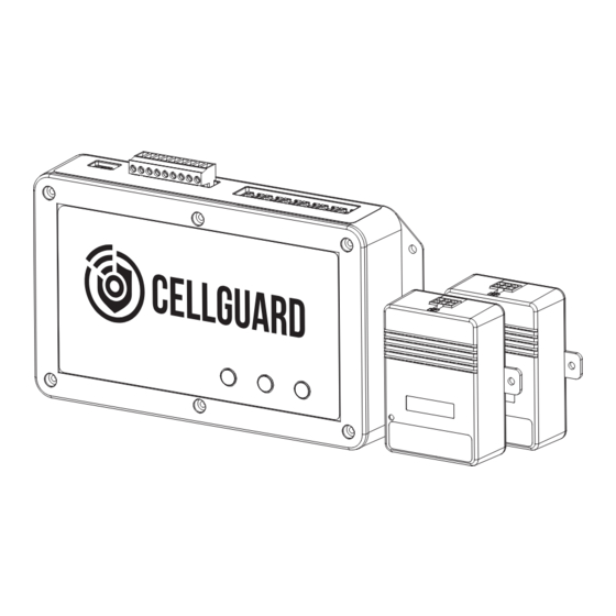
Technical Overview The Franklin Electric Wired Battery Monitoring System (BMS) consists of three primary components: • Battery Sensor – which measures voltage, temperature, and internal resistance of batteries. • String Sensor – which detects discharge events, measures battery string current, and ambient temperature. -
Page 9: System Components
System Components COM 3 COM 2 COM 1 ETHERNET USB-A ALARM POWER STATUS USB-B Component List 1. Base Coordinator Unit (BCU) 2. Battery Sensor 3. String Sensor 4. Current Transducer (CT) 5. UNITE™ Asset Management Database Standard Configuration • Allows online monitoring of: •... -
Page 10: Base Coordinator Unit (Bcu)
3.1.1 Base Coordinator Unit (BCU) General Functions • Connects through either an Ethernet (RJ-45) providing centralized management and the ability to view the health of battery string. • Read monitored values one-by-one providing analysis and processing of data received from sensors. •... -
Page 11: Battery Sensors
3.1.2 Battery Sensors • Monitor voltage, internal resistance and temperature of each battery, uploading the data through a COM port. • Are powered by the monitored battery. • 2 V Sensor, 2 V @ 13 mA • 6 V Sensor, 6 V @ 7 mA •... -
Page 12: Dimensions & Identification
Dimensions & Identification 3.2.1 Base Coordinator Unit (BCU) 1. Ethernet Port 2. USB-A Port 3. USB-B Port 4. Power Input 5. TC String Sensor Power TOP VIEW 6. Form C Relay Output 9.375" 7. Auxiliary Inputs (2) 238 mm 8. Com Ports (3) 1.625"... -
Page 13: Battery Sensor
3.2.2 Battery Sensor 1. Battery cable harness connector 2. COM1 / COM2 Ports 3. Indicator Light 3.36" 1.14" 60 mm 29 mm TOP VIEW 3.27" 83 mm COM1 COM2 BOTTOM VIEW FRONT VIEW SIDE VIEW 3.2.3 String Sensor 1. CT cable harness connector Module Port 2. -
Page 14: Specifications
Specifications Environment Feature Description Location Indoor Use Only Temperature Range 14° F – 122° F (-10° C – 50° C) Relative Humidity 5–95% RH Altitude Up to 6562' (2000 M) Pollution Degree Monitoring Capability Feature Description Maximum Batteries Per String BCU String Maximum BCU Battery Maximum General Weight &... -
Page 15: Accessories
Approvals & Certifications Agency Type / Document » CISPR 11 » IEC 61000-4-2 » IEC 61000-4-3 EMC Certification » IEC 61000-4-4 » IEC 61000-4-5 » IEC 61000-4-6 » IEC 61000-4-11 CE & FCC » Compliance Accessories TABLE 3.2 Accessory Description Product Image Installed on battery terminal posts. -
Page 16: Installation
• Check all items for damage. • If any item shows damage or is not in accordance with the order, inform Franklin Electric immediately. • Remove the packaging material. • Follow all local laws, rules and regulations regarding disposal of discarded parts, packaging material or items and any subsequent components. -
Page 17: Install Instructions
Install Instructions 4.3.1 Numbering Batteries Before connecting the battery sensors to the batteries, label and number both the battery sensors and batteries clearly. Battery String • The first battery, or battery NO.1, must be the first one on the string's positive terminal, the NO.2 is the battery following the NO.1 battery, and so on: •... -
Page 18: Battery Terminal Tabs
STRING 6 Address: 246 STRING 5 Address: 245 STRING 4 Address: 244 STRING 3 Address: 243 STRING 2 Address: 242 STRING 1 Address: 241 COM 3 COM 2 COM 1 ETHERNET USB-A ALARM POWER STATUS USB-B 4.3.2 Battery Terminal Tabs Install the U-type battery terminal tabs (sold separately) on each post on top of the batteries to be monitored. -
Page 19: Installing Battery Sensor Cables
4.3.2.1 Installing Battery Sensor Cables 1. Attach the appropriate end of the battery sensor cable to the tabs on the U-type battery terminal tabs. 2. Plug the battery sensor cable into the battery sensor connector. 4.3.2.2 Creating Custom Length Sensor Cables IMPORTANT: You must use an RJ-22 crimping tool. -
Page 20: Addressing Battery Sensors
4.3.2.3 Addressing Battery Sensors Power Light 1. Make sure the sensors are secured on the batteries, and confirm the power light in the lower left corner is green. COM1 2. To use the Address Modifier (provided): • Connect the connector wire to the Address Modifier and COM1 of the sensor. -
Page 21: Connecting Bcu & String / Battery Sensor Com Ports
4.3.3 Connecting BCU & String / Battery Sensor COM Ports a. COM1 Ports on the BCU: • Facing BCU COM Ports. COM1 left port to either String Sensor Port. • Facing BCU COM Ports. COM1 right port to COM 2 port of the last battery sensor in String 1 (or String 2 if configuring two strings). -
Page 22: Connecting String Sensor Com Ports (Series)
4.3.3.1 Connecting String Sensor COM Ports (Series) NOTE: This wiring method uses the same COM port where in String 2, battery sensors must continue numeric sequence. STRING 1 STRING 2 First BAT Last BAT First BAT Last BAT String 1 String 1 String 2 String 2... -
Page 23: Connecting Bcu & String Sensor Power
4.3.4 Connecting BCU & String Sensor Power IMPORTANT: These terminals are at the far end of the terminal strip, to the left of J1. • RED (+) on left. • BLACK (–) on right. String Sensor • String (12–13 VDC - @ 1 W - from the BCU): •... -
Page 24: Connecting Bcu To Power Supply
4.3.6 Connecting BCU To Power Supply 1. Wire the input power cables to the input ports of the power supply. 2. Wire the cables of the 2-pin connector to the output of the power supply. 3. Wire the input power to the necessary input power. 4. - Page 25 CGBC-AC-264-WD (OPTION) POWER SUPPLY Neutral (N) VAC (Vi) Line (L) VAC (Vi) NEUTRAL NOTE: EU colors are – Neutral (BLUE) and Line (BROWN). CGBC-DC-1500-WD Most positive part of a battery string POWER SUPPLY Most negative part of a battery string...
-
Page 26: Commissioning
Commissioning NOTE: If BCU is already networked, you can access the BCU by directly connecting over the same network as the BCU using Chrome®, Firefox™, or Safari®. Connecting A PC To The BCU The Web Browser Interface of the BCU is accessible through PC via a network connection. -
Page 27: Checking Ethernet Communication
5.1.2.2 Checking Ethernet Communication 1. Locate the Ethernet port on the BCU. 2. Verify the orange RX light (right side of the Ethernet port relative to the connector clasp in the down position) is flashing to confirm data is being received. 3. -
Page 28: Configuring Tcp/Ip Settings On The Pc
5.1.2.5 Configuring TCP/IP Settings On The PC 5.1.2.5.1 If “Obtain An IP Address Automatically” Is Selected If “Obtain an IP address automatically” is currently selected in the Internet Protocol Version 4 (TCP/IPv4) Properties dialog box: 1. Select the “Alternate Configuration” tab. 2. -
Page 29: Initial Web Browser Interface Setup
Once the password is set, if it is forgotten, the user will need to use a backup code or wait to login until Franklin Electric Technical Support is able to assist the user with resetting it. For further information on backup codes, see § 4.9.3. - Page 30 Setting Configuration Errors 1. Navigate to Settings > Configurations to view Configuration Errors. 2. Select Show Errors to view required system parameters. 3. Populate Site Name and Battery Data for system (Press the ENTER key to save parameters). a. Site Name – Physical name of site; typically, will have a Facility Name, Building Name or other unique identifier.
- Page 31 Setting Session Timeout 1. Navigate to Settings > Configuration. 2. Select Users. 3. Select admin. 4. Set time out to a desired duration. Setting Date / Time 1. Navigate to Settings > Date / Time. 2. Set Time / Date fields. 3.
-
Page 32: Configuration
Configuration • Select “>>” ( ) to expand a group to see the full programming section. • Select “+” ( ) to add a String Battery. • Select “–” ( ) to delete a String, Battery. 5.3.1 Configuring BCU System Parameters NOTE: You must have administrative access to make set up changes. -
Page 33: System Preferences
5.3.1.1 System Preferences Group Parameter Name Parameter Value … System Preferences Language Select a language for the Web Browser Interface. Regional Formats Select the preferred system regional format. … Units Temperature Select the preferred unit for the parameter to display. 5.3.1.2 User Roles Group... -
Page 34: Date/ Time
5.3.1.3 Date/ Time NOTE: • If using a URL, the DNS server must be properly configured in the network settings of the BCU. • If NTP Servers are not programmed, navigate to Settings > Date/Time to set the date and time. •... -
Page 35: Interval Tests
5.3.2.1 Interval Tests Group Parameter Name Parameter Value … Interval Tests G Interval Set the number of days between Internal Resistance tests. VT Interval Set the number of hours between Voltage and Temperature tests. 5.3.2.2 Strings • Click “+” to add string . •... -
Page 36: Batteries
Group Parameter Name Parameter Value … Batteries … Battery Thresholds … String Thresholds 5.3.2.2.1 Batteries NOTE: This section will auto populate using battery Data entry screen. • Updating data on all batteries in string. • Make updates to parameters at string level. •... -
Page 37: Battery Thresholds
5.3.2.2.2 Battery Thresholds Group Parameter Name Parameter Value … Strings … String1 … Batteries … Battery Thresholds … Conductance Enable » Threshold of Internal Resistance that will trigger alarms. » High Alarm » High Warning » Low Warning » Low Alarm …... -
Page 38: String Thresholds
5.3.2.2.3 String Thresholds Group Parameter Name Parameter Value … Strings … String1 … Batteries … Battery Thresholds … String Thresholds … Voltage Enable » Threshold of Voltage that will trigger alarms. » High Alarm » High Warning » Low Warning »... -
Page 39: External Alarm Devices
5.3.2.5 External Alarm Devices Group Parameter Name Parameter Value … External Alarm Devices … External Alarm Device 1 Name Name of External Alarm Device. Digital Input @ Invert Input Severity … External Alarm Device 2 5.3.2.6 External Analog Devices Group Parameter Name Parameter Value …... -
Page 40: Downloading A Configuration File
5.3.3 Downloading A Configuration File To download a full site configuration: 1. Select “Download”. 2. Open the “Downloads” folder in file explorer and save the configuration file to the desired location. 3. Rename the file with a name that includes the site it represents and the date. NOTE: The user may need to temporarily disable any pop-up blocker to download the configuration. -
Page 41: Verify Installation & Configuration
5.3.4 Verify Installation & Configuration IMPORTANT: Use this tool to test communications between sensors and CONVERGE™ to ensure the system is set up correctly. • Go to; Tools > Manual Operations • Manual Operations – used to test both individual sensors and entire strings. •... -
Page 42: Communication > Protocols
5.3.5.2 Communication > Protocols 5.3.5.2.1 CELLTRAQ™ IR Group Parameter Name Parameter Value … Communication … Protocols … Celltraq IR Enabled » Yes or No » Must be set to Yes and at least one battery string must be created for “CELLTRAQ™ IR Commission”... -
Page 43: Snmp V3
5.3.5.2.3 SNMP v3 NOTE: Set the SNMP Configuration to match the protocol of the device the BCU will communicate to using SNMP. Group Parameter Name Parameter Value … Communication … Protocols … Celltraq IR … Modbus … SNMP SNMP Version SNMP v3 SNMPv3 User Name 12345678910 Authentication Protocol MD5 Authentication Pass Phrase <not set>... -
Page 44: Celltraq™ Ir Commission
Final Parameter Value Configuration Group Parameter Name Parameter Value … MQTT … Connection 1 Name Connection 1 Service Unite Host unite1.franklingrid.com Password » Enter a MQTT password for use with UNITE™ meeting this criteria: » 12–36 characters including one each of the following alpha-numeric characters: A-Z, a-z, 0-9, -_! &@?*+.() Connection Retries Unlimited Connection Retry Interval 1 minute... -
Page 45: Modbus Register
5.3.7 Modbus Register 1. Click Tools>Modbus Registers. 2. Click the string to display the battery register. 3. The Modbus register map is provided upon request. 5.3.8 Diagnostics & Automatic Upgrades Group Parameter Name Parameter Value … Diagnostics Disabled … Remote Syslog Mode TCP / IP …... -
Page 46: Unite
5.3.9 UNITE™ The Base Coordinator Unit (BCU) is the controller component of the CELLGUARD™ Battery Monitoring System (BMS) managing battery sensor test activities, collecting test data, and communicating with the CONVERGE™ web interface to save data in the UNITE™ database. NOTE: Please see document p/n 10000011818, UNITE™... -
Page 47: Appendix
Appendix Related Documents Documentation can be found online at www.franklingrid.com. Related Documents Part Number Description 167-000801 Wired BMS Install Commissioning Checklist UNITE™ Asset Management Database (User Reference Guide) 10000011818 Glossary BCU ....Base Coordinator Unit BMS ....Battery Monitoring System... - Page 48 FUELING SYSTEMS GRID SOLUTIONS EV SYSTEMS 10000014755 r1...
Need help?
Do you have a question about the CELLGUARD CGBC-350-HWD and is the answer not in the manual?
Questions and answers