Table of Contents
Advertisement
Quick Links
FUELING SYSTEMS
GRID SOLUTIONS
CELLGUARD™
EV SYSTEMS
WIRED BATTERY MONITORING SYSTEM
I N S T A L L G U I D E
167-000800 r2
CONTROL MODULES
CGBC-XXX-WD
STRING SENSOR MODULES
CGTC3-600-WD
BATTERY SENSOR MODULES &
ADDRESS MODIFIERS
CGS3-XXX-WD
CGS3-XX-WD
BATTERY HARNESSES &
INTERCONNECT CABLES
CGS3-XXBH-WD
CGS3-XXCBL-WD
CGS3-XXXCBL-WD
CGS3-XXXX-WD
Advertisement
Table of Contents

Related Manuals for Franklin Electric CELLGUARD CGBC WD Series


Summary of Contents for Franklin Electric CELLGUARD CGBC WD Series
- Page 1 FUELING SYSTEMS GRID SOLUTIONS CELLGUARD™ EV SYSTEMS WIRED BATTERY MONITORING SYSTEM I N S T A L L G U I D E 167-000800 r2 CONTROL MODULES CGBC-XXX-WD STRING SENSOR MODULES CGTC3-600-WD BATTERY SENSOR MODULES & ADDRESS MODIFIERS CGS3-XXX-WD CGS3-XX-WD BATTERY HARNESSES &...
- Page 2 Copyright © 2023 Franklin Electric Co., Inc., Madison, WI 53718. All world rights reserved. No part of this publication may be stored in a retrieval system, transmitted, or reproduced in any way, including, but not limited to, photocopy, photograph, magnetic, or other record, without the prior written permission of Franklin Electric.
-
Page 3: Table Of Contents
Contents 1 Introduction ........................5 1.1 Documentation ......................5 1.1.1 Symbol Legend ....................5 2 Safety/Security ........................6 2.1 General Safety Information..................6 2.2 Hazard Assessment ....................6 2.3 Required Personal Protective Equipment (PPEs) ............7 2.4 Cyber Security ......................7 3 Technical Overview ......................8 3.1 System Components ....................8 3.1.1 Base Controller Module (BCM) ................9 3.1.2 Battery (TA) Sensors ..................10 3.1.3 String (TC) Sensors ..................10... - Page 4 4.3.7 Commissioning The BCM ................23 4.3.7.1 Connecting The BCM Web Interface ..........23 4.3.7.2 Using The Integrator Tool ..............24 4.3.7.2.1 Setting Up String Parameters ........24 4.3.7.2.2 Changing Port Settings ..........25 4.3.7.2.3 Changing IR Settings ............26 4.3.7.2.4 Connecting The BCM Web Interface ......26 4.3.7.2.5 Configuring Network Connections .........27 4.3.7.2.6 Performing The Resistance Test ........28 4.3.7.2.7 Configuring The Franklin Interface ........29...
-
Page 5: Introduction
Introduction The CELLGUARD™ Wired Battery Monitoring System (BMS) delivers economical, yet highly accurate and reliable remote health analysis of stationary batteries in applications with high electromagnetic noise. Documentation • This document is intended for qualified and certified installation persons. • Instructions of this document are in English. All other language versions are translations of this original document. -
Page 6: Safety/Security
Safety/Security General Safety Information • Only perform procedures in this document that you are qualified and certified to perform. • Personnel working on or with energized equipment must be authorized by relevant regulatory bodies to carry out such work and must have the appropriate training. -
Page 7: Required Personal Protective Equipment (Ppes)
The manufacturer. Franklin Electric, and its affiliates are not liable for damages and / or losses related to such security breaches, unauthorized access, interference, intrusion,... -
Page 8: Technical Overview
Technical Overview System Components 1. Base Controller Module (BCM) 2. Battery Sensor Module (TA) 3. String Sensor Module (TC) 4. Current Transducer 5. CELLTRAQ™ data management software Standard Configuration • Allows online monitoring of cell voltage, internal resistance, temperature, string voltage, charge / discharge current, and ambient temperature. -
Page 9: Base Controller Module (Bcm)
3.1.1 Base Controller Module (BCM) The BCM • Is connected through either an Ethernet (RJ-45) or a serial port (RS-485) providing centralized management and the ability to view the health of battery string.* • Can read monitoring values one-by-one providing analysis and processing of data received from TAs and TCs. -
Page 10: Battery (Ta) Sensors
3.1.2 Battery (TA) Sensors • Monitor voltage, internal resistance and temperature of each cell, uploading the data through the COM port. • Are powered by the monitored battery. • 1 V Ni-Cd, 13 mA maximum. • 6 V, less than 7 mA. •... -
Page 11: Accessories
Accessories • Battery tabs (acquisition terminal). • The Address Modifier, p/n CGS3-AMM-WD is used to address TAs and TCs. • The Interconnect cable is used to connect TAs and TCs to the BCM and is included with sensors. Cables are available in 30, 70, 100 and 800 cm lengths. •... -
Page 12: Dimensions & Identification
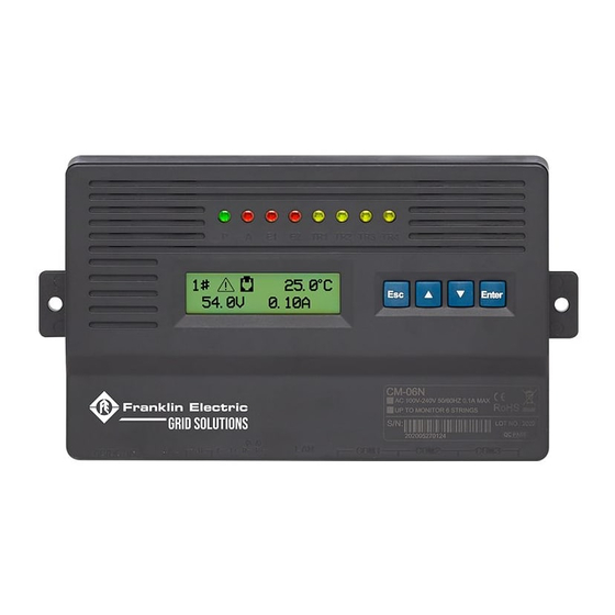
Dimensions & Identification 3.3.1 Base Controller Module (BCM) 1. Alarm indicator lights 2. Power input 3. Power output 4. Dry contact 5. Upload port (COM4) 6. LAN port 7. Communication ports (COM1–COM3) Indicator Lights P – Power light A – Alarm light E1 –... -
Page 13: Battery Sensor Components (Ta)
3.3.2 Battery Sensor Components (TA) 1. Indicator light 2. Battery connection port 3. COM port (COM1–COM2) 3.3.3 String Sensor Components (TC) 1. Indicator light 2. Current transducer connection port 3. COM port (COM1–COM2) 4. Power input... -
Page 14: Installation
• Check all items for damage. • If any item shows damage or is not in accordance with the order, inform Franklin Electric immediately. • Remove the packaging material. • Follow all local laws, rules and regulations regarding disposal of discarded parts, packaging material or items and any subsequent components. -
Page 15: Install Instructions
Install Instructions 4.3.1 Numbering Batteries Before connecting the TAs to the batteries, label and number both the TAs and batteries clearly. Battery String • The first battery, or battery NO.1, must be the first one on the string's most positive terminal, the NO.2 is the battery following the NO.1 battery, and so on: •... -
Page 16: Sensor Installation
4.3.2 Sensor Installation Install the U-type acquisition terminals (provided) on each post on top of the batteries to be monitored. Install the terminals in the following order: • U-type acquisition terminals > Flat washer > Spring washer > Nut (or bolt). Battery Connector U-type Acquisition Terminal Hex Nut... -
Page 17: Installing Sensor Cables
4.3.2.1 Installing Sensor Cables Attach the appropriate end of the sensor cable to the tabs on the U-type acquisition terminal, and then plug the sensor cable into the sensor module connector. 4.3.2.2 Crimping Sensor Cables IMPORTANT: You must use an RJ-22 crimping tool. -
Page 18: Addressing Sensors
4.3.2.3 Addressing Sensors Power Light 1. Make sure the sensors are secured on the batteries, and confirm the power light in the lower left corner is green. COM1 2. To use the TA address modifier (provided): • Connect the connector wire to the TA address modifier and COM1 of the sensor. -
Page 19: Connecting The Bcm & Tc
4.3.2.5 Connecting The BCM & TC The BCM • COM1 on the BCM: • Left side to either COM port on the TC. • Right side from COM2 of the last battery in string 1 or string 2, if using two strings for each COM port. -
Page 20: Wiring Tas
4.3.3 Wiring TAs TA 1 • COM1 and COM2 act identically once they are addressed. • The last sensor in the string, COM2, has a home run back to the right port on COM1 on the BCM. Last sensor in string... -
Page 21: Wiring Multiple String Sensors (Series)
4.3.3.1 Wiring Multiple String Sensors (Series) NOTE: This wiring method uses the same COM port. 4.3.3.2 Wiring Multiple String Sensors (Parallel) NOTE: This wiring method uses multiple COM ports. 4.3.4 Wiring The BCM & TC The BC IMPORTANT: These terminals are at the far end of the terminal strip, to the left of J1. -
Page 22: Connecting The Current Transducer
Multiple TCs Power is daisy chained from one TC to another TC. 4.3.5 Connecting The Current Transducer Use the provided cable to connect to the TC: • A 4-pin terminal connects to the current transducer. • A WHITE, six-section plug connects to the top of TC. •... -
Page 23: Powering The Bcm
4.3.6 Powering The BCM 48 VDC Parasitic Option • Connect the power cable to both the positive and negative ends of the string. • Connect the positive end of the string to the most positive battery in the string. • Connect the negative end of the string to the most negative battery in the string. •... -
Page 24: Using The Integrator Tool
4.3.7.2 Using The Integrator Tool 1. Make sure the unit is connected with an Ethernet cable, and open the Integrator tool. 2. Set IP Address to 192.168.0.105 and Port to 4007. 3. Click OFF to turn on–connect. 4. String 1 appears once connected. 4.3.7.2.1 Setting Up String Parameters 1. -
Page 25: Changing Port Settings
4.3.7.2.2 Changing Port Settings 1. Click Parameters. 2. In the Parameters section, scroll through the list of editable parameters to locate the port parameters you want to modify. 3. Change port numbers as follows: NOTE: The field to right is an editable field. The icon to the left changes to once a change is made. -
Page 26: Changing Ir Settings
4.3.7.2.3 Changing IR Settings Parameters String Information 1. Make sure Correction and Slope Correction are set to 1000. 2. To correct, enter 1 in each field for the correction and slope correction. 3. Click Write. 4. Click Read to confirm the change. 4.3.7.2.4 Connecting The BCM Web Interface 1. -
Page 27: Configuring Network Connections
4.3.7.2.5 Configuring Network Connections The following is the Menu tab on the web Interface landing page: 1. Choose System Parameters on the web Interface landing page Menu tab. 2. Enter the appropriate network information (as shown below), and then click Modify. 3. -
Page 28: Performing The Resistance Test
4.3.7.2.6 Performing The Resistance Test The Resistance Test screen allows you to run an internal resistance test on all sensors. This test MUST be completed at Commissioning. 1. Choose Resistance Test on the web Interface landing page Menu tab. 2. Select the string to be tested, and click Test IR. During the test, each sensor light turns red. -
Page 29: Configuring The Franklin Interface
NOTE: The following files and programs are in the .zip file provided by Franklin Electric. IMPORTANT: Configure the Franklin Interface before you open it. 1. Open the certificate file with Notepad. You must restart the Franklin Interface to make further changes. -
Page 30: Starting The Franklin Interface (Fi)
4.3.7.2.8 Starting The Franklin Interface (FI) NOTE: The Commission Site button remains grayed out until the site parameters are complete. 1. Right click Franklin Interface and choose Run as Administrator. The Franklin directory appears. 2. Right click the directory FRANKLIN. 3. -
Page 31: Commissioning The Site
5. Right click Plant to add strings. Click Plant again to add additional strings. 4.3.7.3 Commissioning The Site The Commission Site button should be active. 1. Click Commission Site. 2. Login to CELLTRAQ™ to confirm the CELLTRAQ™ hierarchy is populated. 3. -
Page 32: Setting Up Batteries
4. Return to the FI. Click Settings, and confirm that scanning has started. 4.3.7.4 Setting Up Batteries 1. Log in to CELLTRAQ™, click x, and expand the hierarchy to the string level. 2. Choose Edit to open the Edit String screen. 3. - Page 33 4. Choose Edit to open the Choose Battery Specification screen. 5. Select Manufacturer to access information about the battery model. Battery specifications cannot be entered if the correct model is not listed. 6. Click the model number of the battery for which to enter specifications. 7.
-
Page 34: Setting Alert Limits
4.3.7.5 Setting Alert Limits 1. Click Config and then Alert Limits. 2. Set parameters for the string and battery alert limits. To correct alert limits, click Edit to change measurements. 3. Click Save when completed. To edit additional measurements, repeat the previous step. -
Page 35: Setting Discharge Limits
4.3.7.5.1 Setting Discharge Limits 1. String current. 2. String voltage: • Choose the Measurement drop-down list. • Enter the limits. • Click Insert. 4.3.7.6 Testing & Confirming Communication 1. Change the times in the certificate file to 2. This sets two minute intervals. 2. -
Page 36: Editing Ip Address Names
4.3.7.7 Editing IP Address Names When the site is active and sending data to CELLTRAQ™, you can modify the IP address to better resemble the site name. 1. Click Config. 2. Click the site. 3. Click Overview. 4. Click Edit. Change the Name field to the name you prefer for the site. 5. -
Page 37: Appendix
Appendix Related Documents Documentation can be found online at www.franklingrid.com. TABLE 5.1 – Related Documents Part Number Description 167-000801 Wired BMS Install Commissioning Checklist Glossary BCM ....Base Controller Module BMS ....Battery Monitoring System FI .....Franklin Interface TA ....Battery Sensor Module TC ....String Sensor Module... - Page 38 Intentionally Blank...
- Page 39 Intentionally Blank...
- Page 40 FUELING SYSTEMS GRID SOLUTIONS EV SYSTEMS 167-000800 r2...
Need help?
Do you have a question about the CELLGUARD CGBC WD Series and is the answer not in the manual?
Questions and answers