
Related Manuals for Franklin Electric INCON DTM-4


Summary of Contents for Franklin Electric INCON DTM-4
- Page 1 FUELING SYSTEMS GRID SOLUTIONS DISTRIBUTION TRANSFORMER MONITOR EV SYSTEMS I N S T A L L G U I D E 10000008964 r2 MODEL DTM-4...
- Page 2 Copyright © 2023 Franklin Electric Co., Inc., Madison, WI 53718. All world rights reserved. No part of this publication may be stored in a retrieval system, transmitted, or reproduced in any way, including, but not limited to, photocopy, photograph, magnetic, or other record, without the prior written permission of Franklin Electric Co., Inc.
-
Page 3: Table Of Contents
Contents 1 Introduction ........................1 1.1 Documentation ......................1 1.1.1 Symbol Legend ....................1 2 Safety/Security ........................2 2.1 General Safety Information..................2 2.2 Hazard Assessment ....................2 2.3 Required Personal Protective Equipment (PPEs) ............2 3 Installation .........................3 3.1 Overview ........................3 3.1.1 Technical Specifications ..................4 3.2 Pre-Installation Inspection ..................4 3.3 Required Tools ......................5 3.4 Instructions .......................5 3.4.1 Mounting ......................5... - Page 4 Intentionally Blank...
-
Page 5: Introduction
• The information given in this document is given as a guide only. It is the installer's responsibility to ensure that correct and safe procedures are followed at the worksite. • This document and related documents are available from: Franklin Electric at www.franklingrid.com. 1.1.1 Symbol Legend Wear Protective Headwear... -
Page 6: Safety/Security
Safety/Security General Safety Information • Only perform procedures in this document that you are qualified and certified to perform. • Personnel working on or with energized equipment must be authorized by relevant regulatory bodies to carry out such work and must have the appropriate training. -
Page 7: Installation
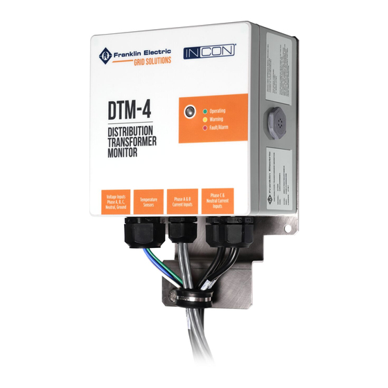
Installation Overview The Distribution Transformer Monitor (DTM-4) is an online continuous performance monitor designed for low voltage transformers. It provides information for the process of Condition-Based Maintenance performing these primary functions: 1. Measurement of transformer output line voltage (direct connection). 2. -
Page 8: Technical Specifications
2. Check all items for damage. 3. If any item shows damage or is not in accordance with the order, inform Franklin Electric Grid Solutions immediately. 4. Remove the packaging material. • Follow all local laws, rules and regulations regarding disposal of discarded... -
Page 9: Required Tools
Required Tools Instructions 3.4.1 Mounting Mount the DTM in a location where the Voltage Leads and Rogowski Coils can reach their intended positions on the transformer. Recommended Mounting Locations are listed below. Always check with your local utility to confirm approved DTM mounting locations before installing. -
Page 10: Dtm-4 Transformer Connections
3.4.2 DTM-4 Transformer Connections NOTE: Pad mount connection illustrations are shown on pages 6 and 7. Pole mounted transformer (single core) connections are shown on page 8. IMPORTANT: Do not cut or attempt to alter the length of the temperature sensors, Rogowski Coil cables or voltage leads. - Page 11 INPUT POWER LOAD IMPORTANT: Roll excess Temperature Sensor, Rowski Coil, or Voltage Lead wire into bundles as needed, and securely fasten them in a safe location. PHASE A CURRENT INPUT PHASE B NEUTRAL PHASE C CURRENT INPUT CURRENT INPUT VOLTAGE LEADS...
- Page 12 Pole Mount (Single Core) Illustrations PHASE A CURRENT INPUT PHASE B NEUTRAL PHASE C CURRENT INPUT CURRENT INPUT LOAD VOLTAGE LEADS INPUT POWER IMPORTANT: Roll excess Temperature Sensor, Rowski Coil, or Voltage Lead wire into bundles as needed, and securely fasten them in a safe location.
-
Page 13: Dtm Setup
3.4.3 DTM Setup All user interface communication including configuration of alarms and settings, data viewing, and alarm resetting is made via the CONVERGE™ web interface. Configuration can be done locally via Wi-Fi using a web browser or remotely through the cellular connection. - Page 14 3. The default URL is https://192.168.170.170. a. A warning will appear saying "No Certificate." b. Click "Accept risks and continue" to access the DTM interface. 192.168.170.170 192.168.170.170 192.168.170.170; 192.168.170.170 4. The first time connecting to the device, a prompt to create a password will appear.
-
Page 15: Configuration
3.4.4 Configuration Navigation: System > Configuration. NOTE: You must press ENTER after typing information in text boxes or data will not be saved. The Configuration page after initial log in: 3.4.4.1 System ID Navigation: Settings > Configuration > System ID. •... -
Page 16: System Preferences
3.4.4.2 System Preferences Navigation: Settings > Configuration > System Preferences. • Language: Set system language. • Regional Formats: Set Regional Format. • Units: Set units of measurement for temperature, density, pressure, length, volume, mass, and power. 3.4.4.3 System Configuration Navigation: Settings > Configuration > System Configuration. Set up with the information of the transformer being monitored. -
Page 17: Date/Time
3.4.4.4 Date/Time Navigation: Settings > Configuration > Date/Time. • Time Zone: Select correct time zone. NOTE: Always set Time Zone first and save changes before setting the clock time on the DTM. Doing so will avoid the time changing to match time zone change. •... -
Page 18: Address Book
3.4.4.5.1 Users Navigation: Settings > Configuration > User. Individual user account creation with associated role, preferences, and units. NOTE: Admin does not require name but does require a password. • Name: Enter name of user. • Password: Enter password for user. •... -
Page 19: Networking
3.4.4.7 Networking Navigation: Settings > Configuration > Networking. Users can define available network connection settings (Wi-Fi and IPv4). 3.4.4.7.1 Wi-Fi Navigation: Settings > Configuration > Networking > Wi-Fi. Set up Wi-Fi with desired information including an alternate SSID and passphrase. •... -
Page 20: Communications
Navigation: Settings > Configuration > Communications. The main protocol used is Message Queuing Telemetry Transport (MQTT) which can be set up to a custom MQTT broker or to Franklin Electric’s UNITE™ Platform by entering the appropriate information. • Enabled: Select YES / NO (sets machine to machine telemetry transport). -
Page 21: Email
3.4.4.10 Email Navigation: Settings > Configuration > Email. • Enabled: Select Yes/No to enable email. • Server: Enter server URL. Example: mail.tanksmtp.com or a static IP address. • Port: Enter port address for SMTP. Example: Port 25. • Sender Host Name: Enter SMTP host address (address of sender (DTM)). •... -
Page 22: Transformer
3.4.4.12 Transformer Navigation: Settings > Configuration > Transformer. Configurable alarm limits are set for the electrical properties of the transformer. Alarm Limits • Winding Load Limit: Limit in Amps that winding load limit will alarm. • Fault Current Limit: Limit in Amps that Fault Current will alarm. •... -
Page 23: Temperature Inputs
3.4.4.13 Temperature Inputs Navigation: Settings > Configuration > Temperature Inputs. Alarm limits are set for the thermal properties of the transformer. • Temperature Warning Limit: Temperature in °F or °C that will trigger alarm. • Temperature Danger Limit: Temperature in °F or °C that will trigger alarm. •... -
Page 24: Appendix
Appendix Wiring Diagrams • Wiring must conform to all applicable federal, state, and local codes. • Control panels are for non-hazardous, indoor use only. • Route RS485 wiring (where applicable) a minimum of 1/4" (6 mm) away from power wiring. 3-Phase 4-Wire, Earthed Neutral, TT VOLTAGES: VAC 120/208... - Page 25 3-Phase 4-Wire, Unearthed Neutral, TT VOLTAGES: VAC 120/208 230/400 277/480 347/600 400/690 480/816 Voltage Leads Rogowski Coils Black DTM-4 Blue White Green (Ground) 3-Phase 3-Wire, Unearthed VOLTAGES: VAC 100-480 Rogowski Voltage Leads Coils Black DTM-4 Blue White Green (Ground) 3-Phase 3-Wire, Earthed Phase VOLTAGES: VAC 100-480 Voltage Leads...
-
Page 26: Status Indicator
Status Indicator A multi-colored LED is used to indicate the status of the DTM and the transformer it monitors, as shown in the following table. This LED can be programmed to remain OFF, if desired (see Section 3.4.11). Table 4.1 – Status Indicators LED Color Status Slow Blinking Green... - Page 27 Intentionally Blank...
- Page 28 FUELING SYSTEMS GRID SOLUTIONS EV SYSTEMS 10000008964 r2...
Need help?
Do you have a question about the INCON DTM-4 and is the answer not in the manual?
Questions and answers