Advertisement
Quick Links
EN_IMPORTANT, RETAIN FOR FUTURE REFERENCE: READ CAREFULLY.
FR_IMPORTANT:A LIRE ATTENTIVEMENT ET À CONSERVER POUR CONSULTATION
ULTÉRIEURE.
ES_IMPORTANTE, LEA Y GUARDE PARA FUTURAS REFERENCIAS.
PT_IMPORTANTE, RETER PARA REFERÊNCIA FUTURA: LEIA ATENTAMENTE.
DE_WICHTIG! SORGFÄLTIG LESEN UND FÜR SPÄTER NACHSCHLAGEN AUFBEWAHREN.
IT _ IMPORTANTE! CONSERVARE IL PRESENTE MANUALE PER FUTURO RIFERIMENTO E
LEGGERLO ATTENTAMENTE.
IN231000329V01_US_UK
D06-096V02
Advertisement

Subscribe to Our Youtube Channel
Related Manuals for PawHut D06-096V02


Summary of Contents for PawHut D06-096V02
- Page 1 IN231000329V01_US_UK D06-096V02 EN_IMPORTANT, RETAIN FOR FUTURE REFERENCE: READ CAREFULLY. FR_IMPORTANT:A LIRE ATTENTIVEMENT ET À CONSERVER POUR CONSULTATION ULTÉRIEURE. ES_IMPORTANTE, LEA Y GUARDE PARA FUTURAS REFERENCIAS. PT_IMPORTANTE, RETER PARA REFERÊNCIA FUTURA: LEIA ATENTAMENTE. DE_WICHTIG! SORGFÄLTIG LESEN UND FÜR SPÄTER NACHSCHLAGEN AUFBEWAHREN.
-
Page 3: Before Using Product
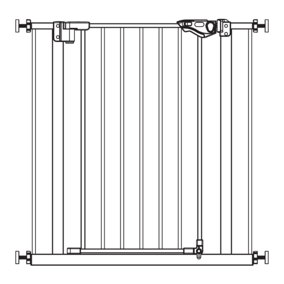
BEFORE USING PRODUCT IMPORTANT • Improper installation could result in the gate becoming unstable or dislodged from the doorway. • Base locks are to be used at all times, on both sides of the gate. • This product will not necessarily prevent all accidents. •... - Page 4 14cm (2.75in) (5.51in) Extension Extension D06-096V02 29 - 33.5inch With 7cm No Extension (2.75in) 81 - 86cm 74 - 79cm 31.5 - 33.5 inch 29 - 31 inch...
- Page 5 INSTALLING YOUR GATE Locate the (4) threaded spindle rods (B). Rotate the adjustment wheels along the threading, eliminating the gap be- tween the adjustment wheel and the rubber foot (Figure 1-1). Figure 1-1 Figure 1-2 NOTE You may notice a slight gap be- tween the gate door latch and the frame (Figure 1-2).
- Page 6 Figure 2-1 Insert the threaded spindle rods with adjustment wheels into the hole on all four corners of the sides of the gate. (Figure 2-1) Figure 2-2 Place the gate in desired opening with 1/8 inch the bottom close to the oor. The dis- tance between the bottom of the gate and the oor should be less than 1/8 Figure 2-3...
- Page 7 Figure 3-1 Insert all 4 threaded spindle rods into the wall cups (Figure 3-1). Tighten the wheels using the spanner tool. (Figure 3-2 and Figure 3-3) Do not over tighten. It may be necessary to hold the thread- ed spindle rods while rotating the ad- Figure 3-2 justment wheels to ensure that the entire unit does not rotate while install-...
- Page 8 OPERATING THE DOOR LATCH Figure 4-1 To Open - Ensure that the base locks at the bottom of the gate door are in the horizontal position (Figure 4-1). Pull the spring lock away from the easy open latch while simultaneously lifting the lock lever upwards (Figure 4-2 and 4-3).
- Page 9 AUTO CLOSE LOCK Figure 5-1 Once the gate is opened,it can close up automatically and lock up. 8 inch When the opening width of the gate is 8 inch, the gate has the function of Automatic Closing (Figure 5-1). Figure 5-2 NOTE When the gate opening width is 23 inch greater than 23 inch, the gate will be...
- Page 10 ADDING A GATE EXTENSION Figure 6-1 Remove the top and bottom threaded spindle rods.(Figure 6-1) Figure 6-2 Assemble the gate and extension as illustrated (Figure 6-2 and 6-3). Reposition the gate and t in ac- cordance with the gate tting instructions.
-
Page 11: Care And Maintenance
REMOVING YOUR GATE FROM THE WALL To remove your gate from the wall, rotate the adjustment wheels on each of the (4) threaded spindle rods to depressurize the gate from its doorway or opening. Then, gently pull or push the gate free from its doorway or opening.
Need help?
Do you have a question about the D06-096V02 and is the answer not in the manual?
Questions and answers