Table of Contents
Advertisement
Advertisement
Table of Contents

Related Manuals for Benchmark BS7680


Summary of Contents for Benchmark BS7680
- Page 1 5554-048 BS7680 MANUAL...
- Page 2 You must register online for your warranty to be valid. It only takes a minute, do it now while you still have your purchase receipt. Register Your Product Online www.benchmark.midlandpowerinc.com/ register-warranty Support for your product is available online, including parts, service center locations, and live expert advice.
- Page 3 Thanks for choosing the BS7680! You're excited to get started, we'll keep this brief. READ THIS ENTIRE GUIDE BEFORE USING THIS PRODUCT AND SAVE FOR LATER USE. This user guide contains important instructions including safety, setup, operation, and maintenance that must be followed. All information in this guide is based on information available at the time of print.
-
Page 4: Table Of Contents
TABLE OF CONTENTS 1. Safety 2. Learn About Your Snowthrower 3. Assembly instructions 4. Pre-Operation Check 5. Starting the Engine 7. Using your snowthrower 7.1 Adjusting the Chute and Chute Deflector 7.2 Engaging the Auger and Impeller 7.3 Engaging the Drive Wheels 7.4 Using the Power Steering Trigger 7.5 Adjusting the Skid Shoe Height 7.6 Using the Headlight... -
Page 5: Safety
This machine is capable of throwing objects that could injure bystanders or cause damage to buildings. When leaving the operating position always disengage the auger, turn off the engine, and remove the key. Never leave a running machine unattended. BS7680... - Page 6 Never operate the snowthrower without proper guards, and other safety protective devices in place and working. Be careful when operating on or crossing gravel drives, walks, or roads. Stay alert for hidden hazards or traffic. Never operate the snowthrower without good visibility or light. Always be sure of your footing, and keep a firm hold on the handles.
- Page 7 Use a tough rubber sheathed flexible cable (according to IEC245 or equivalent standards). The maximum length of the extension cable: 196 feet (60 meters) for cable of 15.5 gauge (1.5mm ); 328 feet (100 meters) for cable of 13.25 gauge (2.5mm BS7680...
- Page 8 1.4 MAINTENANCE SAFETY WARNING! After any maintenance is performed, wash immediately using soap and clean water because repeated exposure to lubricant may cause skin irritation. Allow the engine to cool down and turn off the engine before performing any maintenance.
-
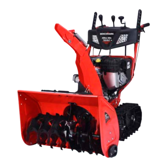
Page 9: Learn About Your Snowthrower
Chute De ector Lever Speed Selector Lever Chute De ector Headlight Chute Impeller Deck Auger Skid Shoes Chute Rotation Crank Auger Height Adjust Trigger Headlight Switch Muf er Power Steering Trigger Headlight Switch Clean Out Tool Heated Grip Switch BS7680... - Page 10 Fuel Cap Oil Cap Power Key Choke Lever Recoil Grip Primer Button Throttle Lever Fuel Shut-off Valve 2.2 CONTROL FUNCTIONS Auger Control Lever Augers and impeller will activate when lever is engaged. Clean Out Tool NEVER clean a clogged impeller or chute with your hands, always use a clean out tool.
- Page 11 Chute Clamps Chute Snowthrower Chute Clamps Chute (Pre-installed) Oil Bottle Spark Plug Wrench Ignition keys Extra Shear Bolts Extra Bow-tie Locking Chute Rotation Cotter Pins Crank Speed Selector Chute De ector Speed Selection Rod Knob Knob Skid Shoes Handle BS7680...
-
Page 12: Assembly Instructions
3. ASSEMBLY INSTRUCTIONS 3.1 Installing the Handle The handle mounting bolts are pre-installed in the correct location. Note the location, then loosen and remove. Thread the bolts through the handle and re-screw into the snowthrower body. - Page 13 On each side of handle as seen from operator’s point of view, insert the bolt and secure with washer and handle knob. Pivot handle grips upwards until aligned with second set of holes in handle. BS7680...
- Page 14 Insert the bolt and secure with washer and handle knob. NOTE Remove the reusable zip tie on the propulsion control lever and auger control lever by pressing the pin lock and pulling the head to remove. Pin Lock Speed Selector Knob Chute De ector Knob...
- Page 15 3.2 Installing the Speed Selector and Chute Deflector Lever Screw the speed selection lever into the top panel. Speed Selector Knob Speed Selector Knob Chute De ector Knob Screw the chute deflector lever into the top panel. Chute De ector Knob BS7680...
- Page 16 3.3 Installing the Speed Selection Rod The speed selection rod needs to match the height of your handle. There are 4 length positions on the speed selection rod that match the 4 height positions of the handles. For example, if you assembled your handles at the tallest position choose the longest length of the speed selector rod.
- Page 17 Speed Spring Pin Clip Add spring and washer to right angle bracket. Push right angle bracket Selection Rod through bottom bracket of speed selection lever, secure with pin clip. Speed Selection Rod Spring Pin Clip BS7680...
- Page 18 3.4 Installing the Chute The chute mounting bolts are pre-installed in the correct location. Note the location, then loosen the bolts. Remove the bolts, washers and chute clamps.
- Page 19 Place chute over, ensuring chute gear teeth mate with worm gear. Fasten the three clamps to chute with washers and bolts. BS7680...
- Page 20 3.5 Installing the Chute Rotation Crank Route the cable under the dashboard and secure it to the chute rotation crank handle. Ensure crank can easily rotate chute with little effort. Chute Rotation Crank Chute Rotation Crank If needed, adjust the worm gear position by loosening, adjusting, and Chute Rotation Crank re-tightening the worm gear mounting bolts.
- Page 21 Find the cable marked C and ensure the cable is loose and not tangled in other cables. Insert the metal rod affixed to the end of the cable into the side bracket of the chute deflector. Side Bracket Metal Rod BS7680...
- Page 22 Secure the metal rod into the bracket with the pin clip. Side Bracket Side Bracket Metal Rod Push down the chute deflector with one hand so that you can thread the Metal Rod thin interior cable into the side bracket of the chute. The two threaded nuts should be on opposite sides of the bracket.
- Page 23 Slide the rubber part over the bolt end to prevent water from entering. Test the chute deflector by operating the chute deflector lever. Adjust position of the two nuts as needed. Chute De ector Lever Chute De ector Lever BS7680...
- Page 24 3.7 Installing the Auger and Propulsion Cables Find the cable marked A and ensure the cable is loose and not tangled in other cables. Thread cable straight up though the panel, to the inside of the control lever. Thread metal end of cable through hole on side of lever. Let cable rest so it hangs straight down.
- Page 25 Lightly pull on the cable to keep it straight, then tighten the two nuts on either side of the bracket. Test the control lever by pushing it into the handle grip. Adjust position of the two nuts as needed. Auger Control Lever BS7680...
- Page 26 Repeat for the other control lever using the propulsion cable marked B.
- Page 27 Remove the mounting screw from the power steering trigger. Position the trigger underneath the right handle. Thread the mounting screw from the top of the handle down into the trigger housing and tighten to ensure the trigger is snug against the handle. BS7680...
- Page 28 Loosen the adjustment nut and adjust the length of the power steering cable until the trigger rests fully open. Tighten the adjustment nut using two wrenches to set the length. Repeat steps 1-6 on the left handle with the trigger marked D.
- Page 29 Thread the skid shoe mounting bolts through the auger housing and skid shoes, loosely attach the nuts. Chute De ector Lever Allow each loose skid shoe to rest on the ground. Tighten the mounting nuts to fix the shoes to this position. BS7680 Chute De ector Lever Chute De ector Lever...
- Page 30 3.10 Installing the Auger Height Adjust Cable Find the cable marked F and ensure the cable is loose and not tangled in other cables. Remove the mounting screw from the auger housing trigger. Position the trigger on the right handle. Thread the mounting screw from the side of the handle into the trigger housing and tighten to ensure the trigger is snug against the handle.
- Page 31 Wire (Black) Connect the black wire to the grounding pin and the panel wire to the other end of the red wire. Panel Wire (Red) Panel Wire Panel Wire (Red) (Red) Grounding Wire (Black) Grounding Grounding Wire (Black) Wire (Black) BS7680...
-
Page 32: Pre-Operation Check
4. PRE-OPERATION CHECK The engine was shipped from the factory without oil. Before you start the engine, ensure that you add oil according to the instructions in this manual. If you start the engine without oil, it will be damaged beyond repair and will not be covered under the warranty. -
Page 33: Using Your Snowthrower
Chute De ector Lever Chute Rotation Crank Rotate the chute rotation crank to set the direction of the discharge chute. Use the chute deflector lever to move the deflector up or down. Raise the chute deflector lever to throw snow further. BS7680... -
Page 34: Engaging The Auger And Impeller
7.2 ENGAGING THE AUGER AND IMPELLER Propulsion Control Auger Control Lever Lever Fully press the auger control lever into the grip of the left handle to engage the auger and impeller. Auger Control Lever Propulsion Control Lever Auger Control Propulsion Control Lever Lever With one-hand control feature, if the propulsion control lever is engaged with your... -
Page 35: Engaging The Drive Wheels
To stop, release the propulsion control lever. Unit must stop immediately. If it does not: Adjust the traction control cable. See Propulsion Control Auger Control Adjusting the Auger and Propulsion Cable. Lever Auger Control Lever Lever Propulsion Control Lever BS7680... -
Page 36: Using The Power Steering Trigger
7.4 USING THE POWER STEERING TRIGGER The model BS7680 is equipped with a power steering feature. A small trigger under each hand grip controls the steering of the machine. Engage the self propulsion lever to move the machine forward. Pull up on the left trigger to turn left. -
Page 37: Adjusting The Skid Shoe Height
This will help prevent rocks and other debris from being picked up and thrown by the auger and impeller. Allow each loose skid shoe to rest on the ground’s surface, then tighten the mounting nuts. BS7680... -
Page 38: Using The Headlight
7.6 USING THE HEADLIGHT To illuminate the area in front of the snowthrower, activate the headlight by turning the headlight switch to ON. Right Headlight Right Headlight Left Headlight 7.7 USING THE HEATED HAND GRIPS Left Headlight To keep your hands warm in cold weather, activate the heated hand grips by turning the heated grips switch to ON. -
Page 39: Clearing A Clogged Discharge Chute
Place the unit on a level surface, turn the fuel shut-off valve to CLOSED, and remove the POWER key. Ensure that the impeller has stopped rotating. Use a clean-out tool to remove snow from the discharge chute. NEVER clear a clogged discharge chute with your hands! Retaining Pin with Pull Ring BS7680... -
Page 40: Using The Auger Height Adjust Trigger
7.9 USING THE AUGER HEIGHT ADJUST TRIGGER The auger height adjust trigger is used to select the position of the auger housing to match the operating surface. Choose the right height for gravel driveways, asphalt, hard impacted snow, or lift up all the way for speedy travel. High - Transport / Snow-covered Gravel ... -
Page 41: Maintenance
Look and listen for exhaust leaks while the engine is running. Have all the leaks repaired before continuing operation. Check for dirt and debris and clean as necessary . Check the engine oil level and add oil as necessary. BS7680... -
Page 42: Maintenance Schedule
8.1 MAINTENANCE SCHEDULE Refer to Briggs and Stratton engine owner's manual. 8.2 CHANGING THE ENGINE OIL Refer to Briggs and Stratton engine owner's manual. 8.3 SPARK PLUG SERVICE Refer to Briggs and Stratton engine owner's manual. 8.4 SPARK ARRESTER MAINTENANCE Refer to Briggs and Stratton engine owner's manual. -
Page 43: Adjusting The Auger And Propulsion Cable
- Both controls should remain engaged. ii. Release the propulsion control lever - Both controls must release. If the unit does not operate as described, DO NOT use it. Contact customer support to have the unit inspected, adjusted, or repaired. BS7680... -
Page 44: Adjusting The Power Steering Cables
8.8 ADJUSTING THE POWER STEERING CABLES The power steering cables may stretch after repeated usage during the first year of operation. If the cable has stretched, it may prevent the drive gears from disengaging when the control is activated. Place the unit on a level surface, turn the fuel shut-off valve to CLOSED, Speed Selector Knob and remove the POWER key. -
Page 45: Replacing The Auger Shear Bolt
Remove the existing shear bolt and pin clip. Speed Selector Lever Add grease to the auger shaft assembly. Spin the auger to lubricate the auger shaft. Align the bolt holes. Install a new shear bolt through the auger shaft and secure with a pin clip. BS7680... -
Page 46: Replacing The Scraper Bar
with Pull Ring 8.10 REPLACING THE SCRAPER BAR Scraper Bar Over time the scraper bar will gradually wear and need replacement. Place the unit on a level surface, turn the fuel shut-off valve to CLOSED, and remove the POWER key. Loosen the retaining nuts and bolts and remove the scraper bar. -
Page 47: Emission Control System
Hard starting or shut down after starting. Unstable idle speed. Shut down or backfire after applying an electrical load. Backfire or after fire. Black smoke and/or excessive fuel consumption. BS7680... - Page 48 Replacement parts and accessories The parts making up the emission control system in your product’s engine have been specifically approved and certified by the regulatory agencies. You can trust that the replacement parts supplied by customer service have been manufactured to the same production standard as the original parts.
-
Page 49: Transportation & Storage
Avoid exposing the snowthrower to prolonged direct sunlight while in an enclosed vehicle. The high temperature inside the vehicle could cause fuel to vaporize resulting in a possible explosion. Drain the snowthrower of fuel and oil before being transported on rough roads. BS7680... - Page 50 Storage Gasoline can oxidize in as little as 30 days, causing gum and varnish to build up in fuel system components. NOTE Ensure that the storage area is free of excess humidity and dust. Storage Duration Preparation Required Less than 1 Month ...
-
Page 51: Troubleshooting
FAST position, and crank until the engine starts. Engine is hard to start Water in fuel, or old Fill with fresh fuel. fuel. or runs poorly. Fuel cap vent is Clear vent or replace fuel cap. blocked. BS7680... - Page 52 Excessive vibration. Loose parts or Stop engine immediately. damaged impeller. Tighten all hardware. If vibration continues, have the unit serviced by an Authorized Dealer. Snowthrower does Traction control cable See Adjusting the Auger and out of adjustment. Traction Cable. not stop when traction control lever is released.
-
Page 53: Technical Specifications
Relative humidity 60% correction factor C-0.01 Relative humidity 80% correction factor C -0.02 Relative humidity 90% correction factor C-0.03 Relative humidity 100% correction factor C-0.04 Example: Rated power ( PN ) 2.8kVA snowthrower (Altitude: 1000m) Ambient temperature: 35°C, Relative humidity: 80% P=Pn*(C-0.02)=2.8*(0.82-0.02)=2.24kVA BS7680... -
Page 54: Limited Warranty
13. LIMITED WARRANTY This product is distributed by: Midland Power Inc. 376 Magnetic Drive, Toronto, ON M3J 2C4, Canada Warranty Briggs and Stratton engine is warranted for a period of 2 years by Briggs and Stratton and is not covered by the below Midland Power Inc. Warranty. Contact Briggs and Stratton Canada at www.briggsandstratton.com for more information. - Page 55 workmanship or material; e. Normal maintenance services, as outlined in the user guide and intended for a consumer to perform; Replacement of parts made in connection with normal maintenance services including oils, adhesives, additives, fuel, filters, brushes, belts, lubricants, spark plugs, gaskets, seals, fasteners, wires, tubes, pipes, fittings, wheels, batteries, and other expendables susceptible to natural wear;...
- Page 56 injection system, the ignition system, and catalytic converter. Also included may be hoses, connectors, and other emission-related assemblies. Emission Control System Warranty Parts: This list applies to parts supplied by Midland Power Inc. and does not cover parts supplied by the equipment manufacturer. Please see the original equipment manufacturer’s emissions warranty for non-Midland Power Inc.
- Page 57 Customer Service Online: www.benchmark.midlandpowerinc.com E-mail: support@midlandpowerinc.com Toll Free: 1-877-528-3772 Enjoy! Be sure to check www.benchmark.midlandpowerinc.com for updates regarding your product.
- Page 58 BS7680...
Need help?
Do you have a question about the BS7680 and is the answer not in the manual?
Questions and answers
ou trouve les piece de souffeuse bs7680
Parts for the Benchmark BS7680 blower are available online at www.benchmark.midlandpowerinc.com.
This answer is automatically generated
how to tight the belt
How to replace impeller pinÉÉ