Table of Contents
Advertisement
Quick Links
Service Bulletin
SB-6-371-1
Replaces SB-6-371-H
The Right
Way To Finish-
Important:
Before
using
this
equip-
ment, read all safety precautions
and in-
structions.
Keep for future use.
See" ACCESSORIES"
section for connections
for riser, gauge,
tee, inlet swivel
and ball
valves.
4. Periodically
clean exterior
of regulator
with solvent soaked cloth.
PARTS REPLACEMENT
The HGB regulator
may be serviced
without
removing
it from the line.
OPERATION
Fluid pressure
adjustment
is done with a re-
movable
key (1). Insert large end of key into
top of regulator.
Turn clockwise
to increase
fluid pressure, counterclockwise
to decrease
fluid pressure.
~
Note
Relieve
line pressure
before
servic-
ing regulator.
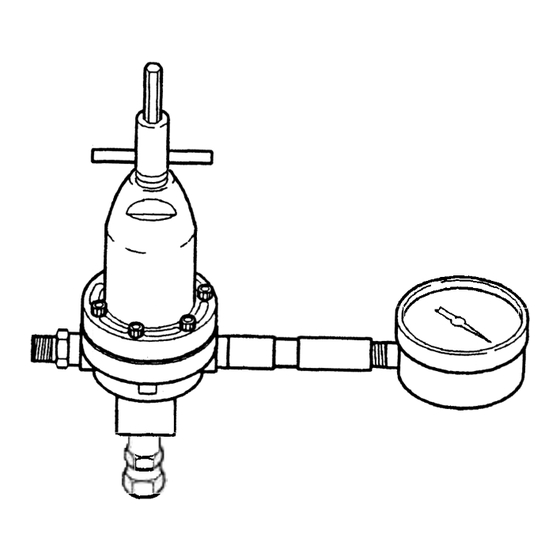
Model HGB-502
Regulator Assembly
Only
Fluid pressure adjustment
can also be accom-
plished
remotely
with air control:
Remove six socket head cap screws (2) with
a 5/32" Allen wrench.
The small end of the
adjusting
key (1) may be used for this pur-
pose.
Model
HGB-508
Includes HGB-502 regulator
plus gauge,
riser tube and
fittings.
1. Turn adjusting
key (1) fully counterclock-
wise turning
the regulator
off.
2. Remove adjusting
key (1).
3. Install a 1/4" NPT(M) fitting
H-2008 for air
hose connection.
4. Use a regulated
air supply to adjust fluid
pressure
regulator.
PREVENTIVE
MAINTENANCE
Periodic
cleaning
of regulator
with a solvent
compatible
with the material
being used is
recommended.
~
r
To clean material
from the regulated
mate-
rial line and the regulator,
these steps should
be followed:
.
SPECIFICATIONS:
Height:
5" (excluding
adjusting
key)
Width:
2-7/8"
1. Relieve supply
line pressure.
2. Using the small end of the adjusting
key
(1 ), engage
the regulator
and screw
it
down
tight.
This holds the valve off its
seat.
Also, the key may be used in this
position
to prevent
waste from entering
the regulator when spray booth is cleaned.
3. Blow material
back through
the regulated
line by introducing
air pressure
into the
line down stream from the regulator.
With
spray gun attached,
this can be done by
loosening
air cap ring on gun, holding
cloth over air cap and pulling trigger.
This
forces air in a reverse path through
spray
gun and air forces material
back through
regulated
material
line.
To Replace Diaphragm:
1. The diaphragm
socket (8) has an arrow
stamped
on top. Curl the edge of
the diaphragm
up where the arrows point.
2. Slip the diaphragm
assembly
out from
under the valve stem nut (C) so the nut is
released from the socket (8).
3. Remove
nut (A) and pull off diaphragms
(7).
Install
2 new
diaphragms
over
threaded
end of the socket
(8). Convex
sides of each diaphragm
must be toward
threaded
end.
4. Apply
retaining
compound
to
male
threads
as shown and install nut (A).
5. Install diaphragm
into body by again curl-
ing the edges of the diaphragms.
6. Slip socket (8) under valve stem nut (C).
7. Reassemble
regulator
body. Tighten all six
cap screws
evenly
to 65 to 75 in./lbs.
torque.
Inlet Pressure
I
Regulated
I
Max. FlUid
/
Max. I Min. Outlet Press.
Flow
Connectio~s
175 ps~l~psi I 10-75 psi I 8 gal/min. I ~~PT(FI
Maximum
temperature
180°F.
INSTALLATION
The HGB regulator
is provided
with two side
outlet ports and one bottom inlet port, all 3/8"
NPT(F). The regulator
may be installed
either
vertically
or horizontally
for flexibility
of
installation.
In either
case, riser and gauge
should
be mounted
vertically.
The HGB-508
includes
gauge,
riser
tube
and
fittings
factory
installed.
To Service Valve Assembly:
1. Valve assembly
can be removed
from the
body with a 3/4" socket wrench.
2. Remove nut (C) and discard stem and seat
(9).
3. Reassemble.
Apply
retaining
compound
to male threads
on stem and tighten
nut
as shown.
4. When reinstalling,
tighten valve assembly
to 20 to 25 in./lbs. torque.
Since the gauge operates
on air trapped
in
the riser, a rise is always necessary. Any leaks
in riser
or gauge
connections
will
permit
this trapped
airto escape thus allowing
paint
to get into the gauge causing damage.
~]
It is recommended
that at initial instal-
lation
the material
supply
line should
not be flushed
through
the regulator
because
pipe compound,
chips, scale,
etc., may lodge in the regulator
valve
assembly.
Advertisement
Table of Contents


Need help?
Do you have a question about the HGB and is the answer not in the manual?
Questions and answers