Table of Contents
Advertisement
Quick Links
Advertisement
Table of Contents

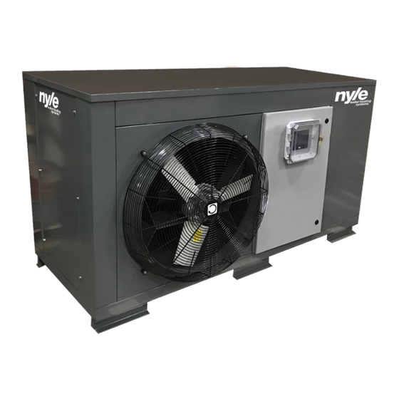
Related Manuals for Nyle C185A


Summary of Contents for Nyle C185A
- Page 1 For R134A units IM-C185A-022124...
-
Page 2: Table Of Contents
Mounting the Heat Pump .......... 15 Seismic Mounting ............15 Water Quality ............17 Water Piping ............17 Piping Concepts ............18 Single-Pass Operation ..........18 Multi-Pass Operation ..........19 Typical Process for Installing Water Piping ....20 HeatWater.com | WaterService@nyle.com | (800) 777-6953 IM-C185A-022124... -
Page 3: Introduction
Introduction Safety Information Thank you for your purchase of a C185A air source The proper installation, use and servicing of this com- heat pump water heater! With this purchase, you now mercial heat pump water heater is extremely import- own one of the most efficient and reliable large-vol- ant to your safety and the safety of others. -
Page 4: Precautions
HeatWater.com | WaterService@nyle.com | (800) 777-6953 IM-C185A-022124... -
Page 5: Purpose
“Single-Pass” or a “Multi-Pass” configura- detailed information is required than is available in this tion, determined when the unit is ordered. Single-Pass manual, please contact Nyle Water Heating Systems means that water is delivered at full usable temperature for additional assistance. -
Page 6: Performance Specifications And Requirements
Performance Specifications and Requirements Table 1: C185A – Performance Specifications 209,500 BTUs/hr Heating Capacity at 70 Deg. F. Heating Capacity at 40 Deg. F. 139,021 BTUs/hr 136,000 BTUs/hr Cooling Capacity at 70 Deg. F. 277 Gallons/hr Recovery Rate (35) 40-120 Deg. F. -
Page 7: Electrical Specifications
Electrical Specifications Table 2: C185A – Electrical Specifications Model C185A–230V C185A–460V Axial Blower Axial Blower Voltage (Volt/Phase/Hz) 208-230/3/60 208-230/3/60 460/3/60 460/3/60 Minimum Circuit Ampacity (MCA) Minimum Overcurrent Protection (MOCP) Running Load Amps (RLA) 76.1 81.5 31.6 34.3 Internal Component Data... -
Page 8: Performance Data
Performance Data Table 3: C185A Expanded Performance Axial Unit Blower Unit Entering Leaving Supply Entering Cooling Water Water Heating Power Power Heating Cooling Combined Heating Cooling Combined Capacity Temp Temp Capacity Input Input Condition (Btu/hr) (°F) (°F) (Btu/hr) (kW) (kW) -
Page 9: Physical Specifications And Clearances
Physical Specifications and Clearances Table 4: C185A Physical Specifications Specification Single-Pass Multi-Pass Water Side Pipe Connections (FPT) 1-1/2" 2" Internal Water Volume (Gallons) Condensate Pipe Connection (MPT) 1" Outside Dimensions (Inches) 72-3/4" L x 45-1/4" W x 43" H Net Weight – Dry (Pounds) 1,350 Net Weight –... -
Page 10: Dimensions
Dimensions Figure 3: C185A Axial Model Dimensions 1" MPT Condensate Drain 27⅜" 1⅝" Typ 36⅝" 37⅝" Mounting Hole Positions 40⅞" 3/4" 7/8" 3½" Front 7/8" Note: All Tolerances +/- 1/8" 44⅝" 4¼" 19½" 2⅝" Bottom Water “OUT” 72¾" Water “IN”... - Page 11 Figure 4: C185A Blower Model Dimensions 1" MPT Condensate Drain 27⅜" 1⅝" Typ 36⅝" 37⅝" Mounting Hole Positions 40⅞" 3/4" 7/8" Front 3½" 7/8" Note: All Tolerances +/- 1/8" 4¼" 19½" 44⅝" 2⅝" Bottom 72¾" Water “OUT” Water “IN” 4⅞"...
-
Page 12: Before Ordering Your Heat Pump
Before Ordering Your Heat Pump F Be sure that qualified refrigeration technicians are available for installation troubleshooting sup- Nyle Water Heating Systems recommends following port and ongoing system maintenance. If this is in this pre-order checklist, to minimize the chances of... -
Page 13: Unit Diagrams And Key Components
Unit Diagrams and Key Components Figure 5: C185A Blower Model Blower Fan Motor Intake Air Inlet (Far Side of Evaporator) (Blower Model Shown) Evaporator (Heat Exchanger) (Air to Refrigerant) Defrost Heating Element Water Outlet Flow Control Valve (Single-Pass Units Only) -
Page 14: Installation
F Ducting to or from remote locations, including in- sulation as necessary. F Control wiring for alarms, BMS interface, and ex- ternal accessories. Nyle recommends running a minimum of one 18/12 control wire and a CAT- 5e/6 wire to ensure that all likely accessories and control functions can be utilized. -
Page 15: Mounting The Heat Pump
IM-C185A-022124 HeatWater.com | WaterService@nyle.com | (800) 777-6953... - Page 16 Figure 9: C185A Mounting Rails Positions and Widths Min. 6 1 " Min. 6 1 " Mounting Rails 35" 19 1 " 66" Figure 10: C185A Unit Center of Gravity 8 " 16 " 16 " 16 " 2 "...
-
Page 17: Water Quality
Where codes and guid- purge process is required to remove any air bubbles from the ance from Nyle are in conflict, advise Nyle or your local lines BEFORE starting up the unit. Failure to purge piping of manufacturer’s representative of the conflict. -
Page 18: Piping Concepts
Where codes and guid- These systems feature the smallest storage and heat pump ance from Nyle are in conflict, advise Nyle or your local capacity requirements, and can be the most efficient meth- manufacturer’s representative of the conflict. -
Page 19: Multi-Pass Operation
11. Multi-Pass only: if multiple tanks are used, a single temp sensor can pick any tank to trigger heating operation. However, the master control acces- sory can be used to add averaging of multiple tank sensors, which is more ideal for multiple, multi-pass tanks. IM-C185A-022124 HeatWater.com | WaterService@nyle.com | (800) 777-6953... -
Page 20: Typical Process For Installing Water Piping
Note: Insulation and heat trace required in freezing climates. CAUTION Nyle recommends all condensate lines be piped to a drain. Failure to control condensate can result in slip/fall conditions, site erosion, water damage, and/or damage to the heat pump water heater itself; which can include complete unit failure not covered by warranty. -
Page 21: Power Wiring
Field Supplied Electricians must create their own entry into the Exterior Disconnects Main Power IN C185A heat pump. There are two points that require Field Installed Wiring creation of an access hole, both marked with “Knock Field Installed Wiring Figure 12. -
Page 22: Control Wiring
Optional BMS Gateway Accessory Contact Ethernet Port 2. Identify the control wire access point on the C185A: this is a pass-through on the rear panel, where the pipes enter and exit the heat pump. RS485 Port B 3. - Page 23 CAT-5 or CAT-6 cable at installation is recommended. heat pump in use, single or multi-pass. Refer to Figure 13 or Figure 14. Table 6: C185A Control Wiring Connections Contact Terminals Wire Type Power...
-
Page 24: Optional Ducting And Ventilation
1. Insulation: all ducting in conditioned spaces re- that the C185A unit removes in real time, such as in quire insulation for energy and condensation con- large commercial mechanical rooms or server farms. -
Page 25: Configuration
Following is guidance for the setup and configuration ler will be active. These are the primary screens that of the heat pump water heater for its standard modes may be used during installation and typical operation. of operation. IM-C185A-022124 HeatWater.com | WaterService@nyle.com | (800) 777-6953... - Page 26 Figure 15: Configuration Screen Figure 16: Diagnose Screen HeatWater.com | WaterService@nyle.com | (800) 777-6953 IM-C185A-022124...
-
Page 27: Single-Pass Configuration
Whether internal single-pass valve is open or closed when system is in standby Closed The C185A should not be set to a LWT higher than 160 Deg F. If LWT is set below Tank Set value, it will be adjusted to Tank Set value. Single-Pass Configuration Multi-Pass Configuration On the “Diagnose”... -
Page 28: Pre-Startup Checklist
F Ducting, if present, is complete, insulated, and connected to terminal grilles/louvers. F Exterior louvers and connecting ductwork will lim- it moisture intrusion, and drain in or out for what moisture does intrude. HeatWater.com | WaterService@nyle.com | (800) 777-6953 IM-C185A-022124... -
Page 29: Startup Procedure
Startup Procedure Nyle Heat Pumps are to be started up by factory au- thorized commissioning agents ONLY. Startup dates are to be requested through your manu- facturer’s representative more than one month before the intended startup. Pre-Startup checklists must be submitted and complete more than 5 days before the startup date. -
Page 30: Initial Troubleshooting
Note: In the rare event that major components end up damaged or defective, you MUST obtain assistance and approval from your rep or from Nyle to authorize warranty replacement, BEFORE the components are removed from service. Problem Check Main power is active at breaker and input terminals. - Page 31 No evidence of oil around compressor base. Ambient is cold enough to make frost. Frost, ice, or snow is visible on coil. Defrost On Defrost function is active All Fan Fault checks are good. Defrost sensor and wiring good. IM-C185A-022124 HeatWater.com | WaterService@nyle.com | (800) 777-6953...
- Page 32 Tank Sensor and wiring are good. Tank Probe is not connected in non- Tank Probe Fault BMS system. BMS system, if present, is connected. Electrical or Temperature problem with M Protection Power Monitor and wiring are good. compressor. HeatWater.com | WaterService@nyle.com | (800) 777-6953 IM-C185A-022124...
-
Page 33: Routine Maintenance
F Inspect and clear any louvers or grilles in at- tached ducting. F Isolate, inspect, and clean any wye strainers on the heat pump piping. F Inspect all attached piping and ducting for water leaks and/or uncontrolled condensation. IM-C185A-022124 HeatWater.com | WaterService@nyle.com | (800) 777-6953... -
Page 34: Limited Warranty
Limited Warranty (6) sized in accordance with proper sizing techniques for commercial heat pump water Nyle Water Heating Systems, the warrantor, extends heaters; the following LIMITED WARRANTY to the original own- er of this commercial heat pump water heater subject... -
Page 35: Service Log
Service Log Issue Description Date Servicer IM-C185A-022124 HeatWater.com | WaterService@nyle.com | (800) 777-6953... - Page 36 690 Maine Ave Bangor, ME 04401 1-800-777-6953 Nyle Water Heating Systems engages in continuous improvement. Sequences, features and capabilities can change without notice at any time. Refer to most current documentation prior to installation or commissioning of all equipment.
Need help?
Do you have a question about the C185A and is the answer not in the manual?
Questions and answers