Table of Contents
Advertisement
Available languages
Available languages
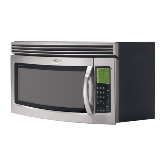
MICROWAVE HOOD COMBINATION
This product is suitable for use above electric or gas cooking products up to 36" (91.4 cm) wide.
These installation instructions cover different models. The appearance of your particular model may differ slightly from the
illustration in these installation instructions.
NOTES:
Proper installation is the responsibility of the installer.
Product failure due to improper installation is not covered under the warranty.
COMBINACIÓN MICROONDAS CAMPANA
Este producto puede usarse encima de productos para cocción eléctricos o a gas de 36" (91,4 cm) de ancho o menor.
Estas instrucciones de instalación cubren diferentes modelos. La apariencia de su modelo en particular puede ser
ligeramente diferente de la ilustración en estas instrucciones de instalación.
NOTAS:
La instalación correcta es responsabilidad del instalador.
La falla del producto debida a la instalación inadecuada no está cubierta por la garantía.
MICROWAVE HOOD COMBINATION SAFETY.......................2
VENTING DESIGN SPECIFICATIONS ......................................2
INSTALLATION REQUIREMENTS............................................3
Tools and Parts .......................................................................3
Location Requirements ...........................................................4
Product Dimensions................................................................4
Electrical Requirements ..........................................................5
INSTALLATION INSTRUCTIONS..............................................5
Remove Mounting Plate..........................................................5
Rotate Air Deflector.................................................................5
Locate Wall Stud(s) .................................................................7
Mark Rear Wall ........................................................................8
Drill Holes in Rear Wall............................................................8
Attach Mounting Plate to Wall ................................................9
Prepare Upper Cabinet ...........................................................9
Install Damper Assembly ..................................................... 10
Install the Microwave Oven.................................................. 10
Complete Installation ........................................................... 12
ASSISTANCE........................................................................... 12
Replacement Parts............................................................... 12
Accessories .......................................................................... 12
IMPORTANT: Read Installation Instructions thoroughly before beginning installation. Save Installation Instructions for local house
inspector's use.
IMPORTANTE: Lea las instrucciones de instalación a fondo antes de comenzar la instalación. Guarde las instrucciones para el uso del
inspector local de la casa.
8206198
INSTALLATION INSTRUCTIONS
INSTRUCCIONES DE INSTALACIÓN
Table of Contents / Índice
REQUISITOS DE INSTALACIÓN.......................................................15
Piezas y herramientas .....................................................................15
Requisitos de ubicación..................................................................15
Dimensiones del producto ..............................................................16
Requisitos eléctricos .......................................................................16
INSTRUCCIONES DE INSTALACIÓN ..............................................17
Retire la placa de montaje...............................................................17
Rote el desviador de aire ................................................................17
Ubique el(los) pie(s) derecho(s) de pared........................................19
Marque la pared posterior...............................................................20
Taladrar orificios en la pared posterior ...........................................20
Ajuste la placa de montaje a la pared.............................................21
Preparación del gabinete superior..................................................22
Instale el ensamblaje de la compuerta de tiro ................................22
Instalación del horno de microondas..............................................22
Complete la instalación ...................................................................24
ASISTENCIA .......................................................................................24
Refacciones.....................................................................................24
Accesorios .......................................................................................24
Advertisement
Table of Contents

Subscribe to Our Youtube Channel
Related Manuals for Whirlpool GH6177XPS


Summary of Contents for Whirlpool GH6177XPS
-
Page 1: Table Of Contents
Mark Rear Wall ...8 Drill Holes in Rear Wall...8 Attach Mounting Plate to Wall ...9 Prepare Upper Cabinet ...9 Install Damper Assembly ... 10 Install the Microwave Oven... 10 Complete Installation ... 12 ASSISTANCE... 12 Replacement Parts... 12 Accessories ... 12 IMPORTANT: Read Installation Instructions thoroughly before beginning installation. -
Page 2: Microwave Hood Combination Safety
If venting through the roof, and rectangular to round transition is used, be sure there is at least 3" (7.6 cm) of clearance between the top of the microwave oven and the transition piece. See “Rectangular to Round Transition” illustration. -
Page 3: Installation Requirements
Rectangular to Round Transition NOTE: The minimum 3" (7.6 cm) clearance must exist between the top of the microwave oven and the rectangular to round transition piece so that the damper can open freely and fully. 3" (7.6 cm) A. Roof cap B. -
Page 4: Location Requirements
Grounded electrical outlet inside upper cabinet. See “Electrical Requirements” section. NOTES: If installing the microwave oven near a left sidewall, make sure there is at least 6" (15.2 cm) of clearance between the wall and the microwave oven, so that the door can open fully. -
Page 5: Electrical Requirements
1. Remove any remaining contents from the microwave oven cavity. 2. Remove the mounting plate by peeling off the strips of tape that attach it to the back of the microwave oven, and set the mounting plate aside. A. Back of microwave oven B. - Page 6 A. Microwave oven exhaust port B. Deflector feet C. Air deflector exhaust port (open end) 5. Slide air deflector into the back of the microwave oven as shown, making sure its exhaust port (open end) aligns with the microwave oven exhaust port.
-
Page 7: Locate Wall Stud(S)
NOTE: If no wall studs exist within the cabinet opening, do not install the microwave oven. See illustrations in “Possible Wall Stud Configurations.” Possible Wall Stud Configurations These depictions show examples of preferred installation configurations with the mounting plate. No Wall Studs at Corner Holes... -
Page 8: Mark Rear Wall
Mark Rear Wall The microwave oven must be installed on a minimum of 1 wall stud, preferably 2, using a minimum of 1 lag screw, preferably 2 or more. 1. Using measuring tape, find and clearly mark the vertical centerline of the opening. -
Page 9: Attach Mounting Plate To Wall
The “rear wall” arrows must be against the rear wall so that the holes cut into the upper cabinet align with the holes in the top of the microwave oven. NOTE: If the upper cabinet has a frame around it, trim the template edges so that it fits inside the frame, against the upper cabinet bottom. -
Page 10: Install Damper Assembly
3/8" (10 mm) holes. 2. Make sure the microwave oven door is closed and taped shut. 3. Using 2 or more people, lift microwave oven and hang it on support tabs at the bottom of mounting plate. - Page 11 4. With front of microwave oven still tilted, thread power supply cord through the power supply cord hole in the bottom of the upper cabinet. 5. Rotate microwave oven up toward upper cabinet. NOTE: If venting through the wall, make sure the damper assembly fits easily into the vent tube in the wall cutout.
-
Page 12: Complete Installation
Accessories Filler Panel Kits are available from your dealer to use when installing this microwave oven in a 36" (91.4 cm) or 42" (106.7 cm) wide opening. The filler panels come in pairs. Each panel is 3" (7.6 cm) wide. -
Page 13: Seguridad De La Combinación Microondas Campana.13
SEGURIDAD DE LA COMBINACIÓN MICROONDAS Su seguridad y la seguridad de los demás es muy importante. Hemos incluido muchos mensajes importantes de seguridad en este manual y en su electrodoméstico. todos los mensajes de seguridad. Este es el símbolo de advertencia de seguridad. Este símbolo le llama la atención sobre peligros potenciales que pueden ocasionar la muerte o una lesión a usted y a los demás. - Page 14 Tubo de ajuste rectangular a redondo NOTA: Debe haber un espacio mínimo de 3" (7,6 cm) entre la parte superior del horno de microondas y el tubo de ajuste rectangular a redondo para poder abrir la compuerta libre y completamente. 3"...
-
Page 15: Requisitos De Instalación
REQUISITOS DE INSTALACIÓN Piezas y herramientas Herramientas necesarias Reúna las herramientas y piezas necesarias antes de comenzar la instalación. Lea y siga las instrucciones provistas con cualquiera de las herramientas enlistadas aquí. Cinta de medir Detector de pies derechos Lápiz Llave de tubo de 7/16"... -
Page 16: Dimensiones Del Producto
Dimensiones de instalación NOTA: El contacto de pared de conexión a tierra de 3 terminales debe estar dentro del gabinete superior. Vea la sección “Requisitos eléctricos”. 30" (76,2 cm) mín. 30" (76,2 cm) típico* 66" (167,6 cm) mín. A. Pie derecho de pared 2" x 4" B. -
Page 17: Instrucciones De Instalación
INSTRUCCIONES DE INSTALACIÓN Retire la placa de montaje NOTA: Coloque una cubierta protectora sobre la superficie de trabajo para evitar posibles daños en la misma. 1. Saque el contenido restante de la cavidad del horno de microondas. 2. Para sacar la placa de montaje, pele las bandas de la cinta que la sujetan a la parte posterior del horno de microondas y deje la placa de montaje a un lado. - Page 18 5. Deslice el desviador de aire dentro de la parte posterior del horno de microondas, como se muestra, cerciorándose de que la lumbrera de escape (extremo abierto) esté alineada con la lumbrera de escape del horno de microondas. A. Lumbrera de escape del horno de microondas B.
-
Page 19: Ubique El(Los) Pie(S) Derecho(S) De Pared
Ubique el(los) pie(s) derecho(s) de pared NOTA: Si no hay pies derechos de pared dentro de la abertura del gabinete, no instale el horno de microondas. Vea las ilustraciones en “Posibles configuraciones de los pies derechos de pared”. Posibles configuraciones de los pies derechos de pared Estas representaciones muestran ejemplos de las configuraciones de instalación preferidas con la placa de montaje. -
Page 20: Marque La Pared Posterior
Marque la pared posterior El horno de microondas deberá instalarse como mínimo sobre 1 pie derecho de pared, preferentemente 2, usando un mínimo de 1 tirafondo, preferentemente 2 o más. 1. Con la cinta de medir, ubique y marque claramente la línea central vertical de la abertura. -
Page 21: Ajuste La Placa De Montaje A La Pared
Instalación para un pie derecho de pared en dos orificios de esquina (figura 3) 1. Taladre orificios de 3/16" (5 mm) a través del pie derecho de pared en los 2 orificios de esquina que se marcaron en el paso 3 de “Marcar la pared posterior”. -
Page 22: Preparación Del Gabinete Superior
Pies derechos de pared en los cuatro orificios de esquina (figura 4) 1. Posicione la placa de montaje en la pared, asegurándose de que la parte superior de la placa de montaje esté alineada con el borde frontal del gabinete superior. 2. - Page 23 3. Con la ayuda de 2 o más personas, levante el horno de microondas y cuélguelo de las lengüetas de soporte en la parte inferior de la placa de montaje. NOTA: No tome o use la puerta o la manija de la puerta durante la instalación.
-
Page 24: Complete La Instalación
2. Conecte el ducto de escape al ensamblaje de la compuerta de tiro. A. Ducto de escape B. Ensamblaje de la compuerta de tiro (debajo del ducto de escape) Complete la instalación 1. Vea el Manual de uso y cuidado para obtener las instrucciones sobre cómo instalar filtros en su modelo.
Need help?
Do you have a question about the GH6177XPS and is the answer not in the manual?
Questions and answers