Table of Contents
Advertisement
Quick Links
Advertisement
Table of Contents

Subscribe to Our Youtube Channel
Related Manuals for Humzor NC610


Summary of Contents for Humzor NC610
- Page 1 USER’S MANUAL HUMZOR NC610 Car and Truck OBD2 Scan Tool NC610...
- Page 2 HUMZOR technology adheres to the responsibility of quality and is committed to providing users with high quality and high performance products. Adhere to technology to create advantages, committed to promoting industrial progress through innovation, support enterprise development and achieve product upgrading.
- Page 3 All information, specifications and illustrations in this manual are based on the latest information available at the time of printing. HUMZOR reserves the right to make changes at any time without notice. While information of this manual has been carefully checked...
- Page 4 important that the safety instructions presented throughout this manual be read and understood by all persons operating or coming into contact with the device. There are various procedures, techniques, tools, and parts for servicing vehicles, as well as in the skill of the person doing the work. Because of the vast number of test applications and variations in the products that can be tested with this equipment, we cannot possibly anticipate or provide advice or safety messages to cover every...
- Page 5 gases are poisonous. Put the transmission in PARK (for automatic transmission) or NEUTRAL (for manual transmission) and make sure the parking brake is engaged. Put blocks in front of the drive wheels and never leave the vehicle unattended while testing. Be extra cautious when working around the ignition coil, distributor cap, ignition wires and spark plugs.
-
Page 6: Table Of Contents
CONTENTS 1. Product Instructions 1.1 Product Description 1.2 Specifications 1.3 Accessories Included 1.4 Keyboard 1.5 Power 2. OBD (On-Board Diagnostics) II Introduction 2.1 On-Board Diagnostics(OBD)II 2.2 Data Link Connector (DLC) 3. OBD-II Diagnosis 3.1 Read DTCs (Diagnostic Trouble Codes) 3.2 Clear DTCs 3.3 Live Data 3.4 Freeze Frame Data 3.5 I/M Readiness Monitors... - Page 7 8.2 Help Function 8.3 Unit of Measure 8.4 Beep Setting 8.5 Device Self-Test 8.5.1 Screen Test 8.5.2 LCD Test 8.5.3 Key Test 8.6 Vehicle Coverage 8.7 Protocol Coverage 8.8 Test Mode Coverage 8.9 Product Trouble shooting 9. Warranty 9.1 Limited Three Year Warranty 9.2 Service Procedures...
-
Page 8: Product Instructions
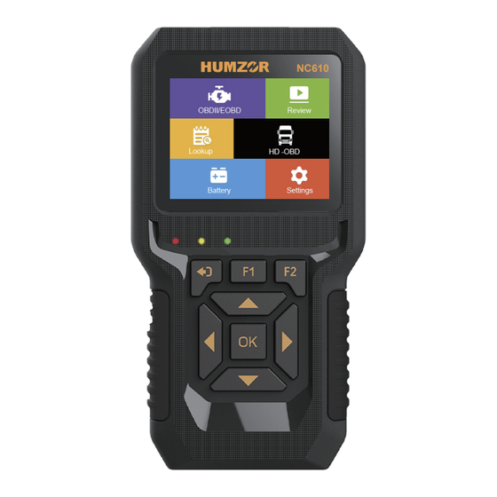
1. Product Instructions 1.1 Product Description NC610 is easy to carry, simple to operate, fast in diagnosis, large in memory, comprehensive in code base, powerful in performance and novel in design. It is a new generation OBDII diagnostic tool tailored for the owner. Data Live, Freeze Frame,... -
Page 9: Specifications
1. LCD Screen: Indicates test results. 2. ESC Button: Returns to the previous screen. Checks Data stream after selecting specific data items. 3. F1 Button: F1 is the help function in the main screen, and the back to the main screen in the diagnostic screen 4. -
Page 10: Power
Figure 1-1-2 Product Display 1.5 Power The scan tool is powered via the vehicle Data Link Connector (DLC). Just follow the steps below to turn on the scan tool: 1. Connect the OBD II Cable to scan tool. 2. Find DLC on vehicle. 3. -
Page 11: Data Link Connector (Dlc)
"OBDII". The OBD II system is designed to monitor emission control systems and key engine components by performing either continuous or periodic tests of specific components and vehicle conditions. When a problem is detected, the OBD II system turns on a warning lamp (MIL) on the vehicle instrument panel to alert the driver typically by the phrase of "Check Engine"... -
Page 12: Obd-Ii Diagnosis
3. OBD-II Diagnosis The OBD II Diagnostics function is a fast-access option that allows you to carry out a quick test on the engine system of OBD II. When more than one vehicle control module is detected by the scan tool, you will be prompted to select the module where the data may be retrieved. - Page 13 problem area and are intended to provide you with a guide as to where a fault might be occurring within a vehicle. There are three types of DTCs: 1. Stored DTCs - A DTC is stored when a fault condition has occurred that meets enough criteria to activate the MIL.
-
Page 14: Read Dtcs (Diagnostic Trouble Codes)
Read DTCs as follows: 1. Use UP/DOWN scroll button to select Read DTC from Diagnostic Menu and press OK button. 2. Use the UP/DOWN scroll button to select Stored DTCs, Pending DTCs, Permanent DTCs or Record DTC from the Read Codes menu and press the OK button.Module [PCM] and Transmission Control Module [TCM]. -
Page 15: Clear Dtcs
UP/DOWN scroll button to select manufacturer and then press OK button to confirm. Figure 3-1-6 select Car Brand Figure 3-1-7 Stored DTC Interface Selection Interface NC610 1. Green light A has no fault code or broken line B has permanent code 2. Red light... -
Page 16: Live Data
by a technician. NOTE: Erasing codes does not mean that trouble codes in ECU have been eliminated completely. As long as there is fault with the vehicle, the trouble codes keep on presenting. This function is performed with key on engine off (ROEO). Do not start the engine. - Page 17 Figure 3-3-1 Data Stream Figure 3-3-2 Data Stream Selection Interface Interface A. View All Items 1. To view complete set of data, use UP/DOWN scroll button to select View All Items from Live Data menu and press the OK button. 2.
- Page 18 Figure 3-3-4 Items Selection Figure 3-3-5 Confirm Items Interface C. View Graphic Items 1. Use the UP/DOWN scroll button to get the desired items and click OK button to confirm. 2. Press ESC to view the selected PIDs. Figure 3-3-6 Graphic Items Display NOTE: Merge Graph can be used to compare four related parameters in graphic mode.
-
Page 19: Freeze Frame Data
3.4 Freeze Frame Data Freeze Frame Data: Operating conditions that are stored when a DTC is stored. Freeze Frame Data allows the technician to view the vehicle's operating parameters at the moment a DTC is detected. For example, the parameters may include engine speed (RPM), engine coolant temperature (ECT), or vehicle speed sensor (VSS)etc. - Page 20 In order for the OBD monitor system to become ready, the vehicle should be driven under a variety of normal operating conditions. These operating conditions may include a mix of highway driving and stop and go, city type driving, and at least one overnight-off period. For specific information on getting your vehicles OBD monitor system ready, please consult your vehicle owner's manual.
-
Page 21: Mil Status
"Not Ready" to pass the emissions inspection. Indicates that a particular monitor being checked has completed its diagnostic testing. Indicates that a particular monitor being checked has not completed its diagnostic testing. The monitor is not supported on that vehicle. 1. -
Page 22: Vehicle Information
The MIL Status allows checking the status of MIL and run time/ distance with Check Engine Light on, run time/distance since DTC cleared. 1. Select MIL from Diagnostic Menu and press OK button. 2. Use the UP/DOWN scroll button to select the item you’d like to check Figure 3-6-1 MIL Status Figure 3-6-2 MIL Status... - Page 23 after erasing a vehicle's control module memory. The On-Board Monitor Test for non-CAN-equipped vehicles retrieves and displays test results for emission-related power train components and systems that are not continuously monitored. The On-Board Monitor Test for CAN-equipped vehicles retrieves and displays test results for emission-related power train components and systems that are and are not continuously monitored.
-
Page 24: Smog Check
Mode 8 (The Component Test) function allows initiating a leak test for the vehicle's EVAP system. The scan tool itself does not perform the leak test, but commands the vehicle's on-board computer to start the test. Different vehicle manufacturers might have different criteria and methods for stopping the test once it has been started. -
Page 25: Fuel Analysis
3.11 Fuel Analysis Fuel Analysis: Analyze the instant, idle speed and average fuel consumptions in the cars. Figure 3-11-1 Fuel Figure 3-11-2 Function Analysis Selection Interface Display Interface 4. HD OBD Diagnosis 4.1 Read DTCs There are three types of DTCs: 1. -
Page 26: Clear Dtcs
1. Use the UP/DOWN scroll button to select Vehicle Information, Read Codes, Erase Codes or Data Stream from the Diagnostic menu and press the OK button. 2. Use UP/DOWN scroll button to select Read Codes from Diagnostic Menu and press OK button. 3. -
Page 27: Live Data
The Clear DTCs function can erase Stored DTC and Pending DTC in ECUs’ memory, but cannot erase the Permanent DTC. Figure 4-2-1 Erase DTC Figure 4-2-2 Clear DTC Selection Interface Confirm Interface Figure 4-2-3 Erase DTC Progress Figure 4-2-4 Clear DTC Information Interface Finish Interface 4.3 Live Data... -
Page 28: Vehicle Information
4.4 Vehicle Information The Vehicle Info. function enables retrieval of Vehicle Identification No. (VIN), Calibration ID Nos.(CINs), Calibration Verification Nos.(CVNs) . Figure 4-4-1 Vehicle Information Interface 5. Battery Test The Battery Test function allows viewing the status and the voltage of the vehicle. Figure 5-1-1 Select battery test Figure 5-1-2 Battery testing interface... -
Page 29: Review
Figure 6-1-1 DTC Look up 1. Use the UP/DOWN scroll button to select DTC Query from Diagnostic Menu and press OK button. 2. Wait for the scan tool to display the DTC Query screen. 3. Press UP/DOWN to change input and press LEFT/RIGHT to select position. -
Page 30: Language Setup
French, German, Spanish, Russian, Chinese,Polish and Italian. 2. Help: Information about the unit and Vehicle diagnostics. 3. Unit of measure: Sets the unit of measure to English or Metric. 4. Beep: Turns On/Off beep. 5. Device Self-Test: Checks if the keyboard, LCD display or the screen is working properly. -
Page 31: Help Function
8.2 Help Function Show users information about the tool, OBD and DataStream. Use the UP/DOWN scroll button to select the desired information and press the OK to view the information. Figure 8-2-1 Help Interface 8.3 Unit of Measurement Metric is the default measurement unit. From Unit of Measure screen, use the OK button to select the desired unit of measurement. -
Page 32: Screen Test
Figure 8-4-1 Beep Set Interface Figure 8-5-1 Device Self-Test 8.5.1 Screen Test The Screen test function checks if the screen display is working properly. Look for errors after the screen color changes. 8.5.2 LCD Test The LCD Test function checks if the LCD display is working normally. - Page 33 compliant vehicles, including those equipped with next-generation protocol- Control Area Network (CAN). It is required by EPA that all 1996 and newer vehicles (cars, light-duty and heavy-duty trucks) sold in the United States must be OBD II compliant and this includes all Domestic.
-
Page 34: Protocol Coverage
8.7 Protocol Coverage Allows different systems and sensors in a vehicle to communi- cate. There are currently five Protocols: SAE_J1850 PWM, SAE_J1850 VPW, ISO15765-4 CAN(11bit),ISO15765-4 CAN(29bit),IS014230-4 KWP(5BPS) IS09141,SAE J1939 Figure 8-7-1 Enter Interface PID-Parameter Identification Data: Data returned by the vehicle's Control Modules to the Scan Tool. -
Page 35: Product Trouble Shooting
Mode $02-Request Powertrain Freeze Frame Data. Mode $03-Request Emission-related stored DTCs. Mode $04-Clear/reset Emission-related diagnostic information. Mode $05-Request Oxygen Sensor Monitoring Test Results(2007 and older vehicles only) Mode $06-Non-continuously Monitored System test results. Mode $07-Request for DTCs (pending) from Continuously Monitored Systems after a single driving cycle has been performed to determine if repair has fixed a problem. -
Page 36: Warranty
1.The sole responsibility of HUMZOR Technology under the Warranty is limited to either the repair or, at the option of HUMZOR Technology, replacement of the scan tool at no charge with Proof of Purchase. The sales receipt may be used for this purpose. -
Page 37: Service Procedures
9.2 Service Procedures If you have any questions, please contact your local store, distributor or visit our website at www.humzor.com. If it becomes necessary to return the scan tool for repair, contact your local distributor for more information. - Page 38 Auto Master. Master Auto ® Shenzhen Hanzhi Technology Co.,Ltd. Add:403 Building C, Bay Area Artificial Intelligence Industrial Park, Xixiang Street, Baoan District, Shenzhen P . C:518100 Tel:+8619924486472/+8619924926599 Email:info@humzor.com www.humzor.com LINKING CAR OWNER & MECHANIC...
Need help?
Do you have a question about the NC610 and is the answer not in the manual?
Questions and answers
можно ли этим сканером подключать не задействованные опции в блоке управления автомобилем