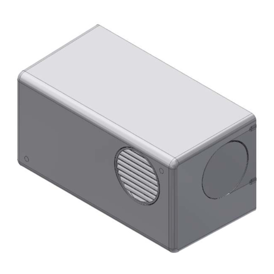
Summary of Contents for AirTech Air+ WALL
- Page 1 Installation & Commissioning Instructions Positive Pressure System Ventilation Unit Air+ WALL AIR+PIV/W PLEASE READ INSTRUCTIONS IN CONJUNCTION WITH THE ILLUSTRATIONS. PLEASE SAVE THESE INSTRUCTIONS...
-
Page 2: Introductory Notes
Installation and Wiring Instructions for the Air+ Wall Positive Ventilation Unit. INTRODUCTORY NOTES The Unit is a positive input ventilation unit, designed to be installed on a wall of a dwelling to continually supply filtered fresh air into the building. The system consists of a fan unit with heater. -
Page 3: Unit Mounting
safe way and understand the hazards involved. Children shall not play with the appliance. Cleaning and user maintenance shall not be made by children without supervision. Precautions must be taken to avoid the back-flow of gases into the room from the open flue of gas or other fuel-burning appliances. Children of less than 3 years should be kept away unless continuously supervised. -
Page 4: Typical Installations
TYPICAL INSTALLATIONS ABS COVER ONLY See Inlet Options 1 or 2 for Install, page 8. 1. Insulate all ducting running from atmosphere and any ducting that passes through an unheated space. Choose either a side or rear inlet position for the unit. FLEX DUCT INSTALL 1. - Page 5 RIGID DUCT INSTALL 1. Securely connect the rigid ducting to the unit’s spigot, using a suitable adhesive. See Outlet Option 3 for Install, page 11. 2. Secure diffuser to the rigid ducting, using a suitable adhesive. 3. The total length of rigid duct in the system (Inlet and outlet) should not exceed 2.5m, with a maximum of two 90°...
-
Page 6: Installation
INSTALLATION The Unit is wall-mounted using the bracket and fixings supplied (or other suitable fasteners). Ensure there is sufficient space around the unit’s base plate, when installing, to allow fitting & removal of the cover for servicing & maintenance. (See image below). The wall should have sufficient strength to support the unit. - Page 7 Feed power supply (and optional Heater Switch cable) through Base plate or bottom left hand side of unit, then through the rear of the foam before securing unit. Hand tighten these 2 screws, when fitting the scroll assembly.
- Page 8 INLET OPTIONS OPTION - 1 OPTION - 2 If installing the unit with the air supply coming through the rear, the metal plate cut-out will need to be removed from base plate and the rear foam case will need to be cut-out before mounting. See next page for details.
- Page 9 Base Plate Snip the three tabs to remove the insert Rear Foam Using the centre mark, cut through the foam housing using a hole...
- Page 10 OUTLET OPTIONS OPTION - 1...
- Page 11 OUTLET OPTIONS OPTION - 2...
- Page 12 OUTLET OPTIONS OPTION - 3...
-
Page 13: Filter Installation
FILTER INSTALLATION Please make sure the filter is fitted correctly and retained on top of the scroll. This will ensure that all the fresh air entering the dwelling has passed through the filter first. Slide filter on top of scroll Push filter over retaining clip to secure it in place. - Page 14 Cover Plates – Grille & Blanking When using the cover plates on the front of the unit, care must be taken when snapping them free. Only the cover plate that is being used in the front of the housing needs to be modified.
- Page 15 WIRING A means for disconnection must be incorporated, in the fixed wiring in accordance with the wiring regulations. WARNING: THE POSITIVE VENTILATION UNIT AND ANCILLARY CONTROL EQUIPMENT MUST BE ISOLATED FROM THE POWER SUPPLY DURING THE INSTALLATION / OR MAINTENANCE. Mains supply voltages (220-240V AC) are present in this equipment which may cause death or serious injury by electric shock.
-
Page 16: Start-Up Sequence
Use this cable clamp on scroll to secure mains power cable. Use this cable clamp on scroll to secure optional Heater Switch cable. Univers 45 Light FOR REFERENCE ONLY In order to have the product switch off in the event of a fire it must be wired using a smoke alarm with a relay system. - Page 17 Lock feature The lock feature will prevent the unit from being adjusted after commissioning as a pass code is required to access the menu. This can be set in the menu to any 3 digit hexadecimal combination. If the lock feature is enabled; when a button is pressed the display will show, – – –. At this point enter the three digit code by first pressing + or –...
-
Page 18: Comfort Mode
Options: press up or down to start choosing the first digit then press mode to set and move to the next digit. Repeat to set the other two digits. Default override code is 999. For most installs the standard features allow for ample adjustability, however in some install situations the advanced features will improve the unit’s performance or acceptability. -
Page 19: Servicing And Maintenance
SERVICING AND MAINTENANCE. WARNING: THE POSITIVE VENTILATIION UNIT AND ANCILLARY CONTROL EQUIPMENT MUST BE ISOLATED FROM THE POWER SUPPLY DURING THE INSTALLATION / OR MAINTENANCE. The fan motor uses sealed ball bearings, and does not require further lubrication. Apart from filter change the Unit contains no user serviceable parts. Under normal conditions;... - Page 20 Spares and accessories available for the Air+ Wall: Spares and Accessories Part Number ABS COVER 479844 SILENCER KIT ROUND TO RECTANGLE ADAPTOR - ∅105mm to 55x110mm 479857 ACOUSTIC FLEXI DUCT 443273 400740 REPLACEMENT 3 BUTTON SCROLL ASSY 479859 FILTER ISO Coarse (G4) FIL10 FILTER ISO ePM2.5 (F7)


Need help?
Do you have a question about the Air+ WALL and is the answer not in the manual?
Questions and answers