Record DFA 127 Technical Manual
Battery backup
Hide thumbs
Also See for DFA 127:
- Instructions manual (103 pages) ,
- User manual (56 pages) ,
- Operating instructions manual (21 pages)

Subscribe to Our Youtube Channel
Related Manuals for Record DFA 127


Summary of Contents for Record DFA 127
- Page 1 Technical Manual DFA Battery Backup Weight 1.25KG Dimensions = 160mm wide x 80mm high x 125mm deep...
- Page 2 G72 0AH The Manufacturer Certifies That; Product: DFA 127 Battery Backup Description: Automatic Door Control Equipment This Equipment is designed to be incorporated into an automatic door set, not to be used independently and must not be “put into service” until the complete door set has been declared compliant to the EC Machine Directive.
- Page 3 This manual contains all the information you may require to install, maintain and service your Battery backup system. The System allows a DFA 127 Swing Door Operator to be used even during mains power fail situations. Safety Your door system has been manufactured to the latest applicable safety standards; in order for you to comply you will need to have the door installed to any relevant safety standards by a qualified engineer.
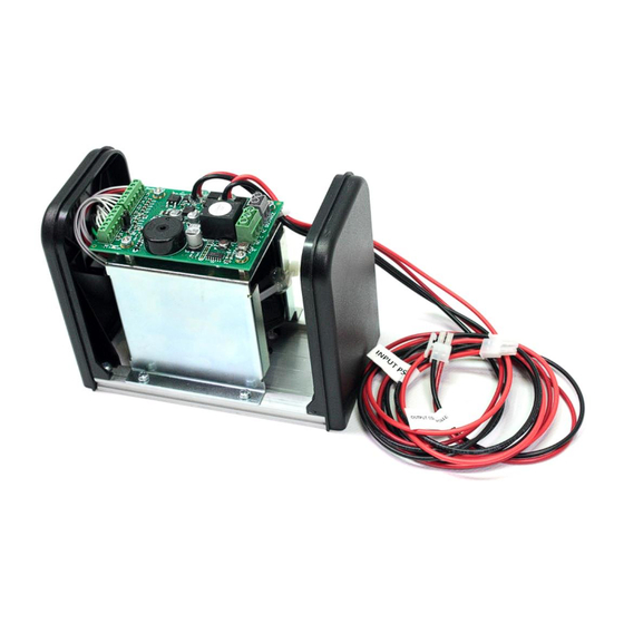
- Page 4 The DFA Battery Backup comes complete in its own housing and at just 16cm long it is a small but powerful battery unit. The case is aluminum “stainless steel” effect and looks seamless against the standard DFA 127 Swing Unit.
- Page 5 1. Remove the cover, end-caps and battery unit from the back plate 2. Fix the unit next to the DFA 127 swing door operator 3. Re-fit the end-caps and battery unit 4. Route your cables to the swing unit by drilling through the end-caps or via any hollow...
- Page 6 5. Output – Fly lead plugs into the control unit of your DFA 127(J) 6. Input – Fly lead plugs directly on to the PSU, under the plastic cover. (I) For a more streamlined look – Cut 8mm off of the back plate and Install as previous but with just the outside end-cap.
- Page 7 For Option B – You must wire from the relay on the Battery Unit to the SSK – When the mains fails the battery will take over but also it will close the relay thus triggering the DFA to stand open. See wiring diagram below - connecting the relay to the DFA 127. Volume When the mains supply has cut off the battery unit will take over in approximately 3 seconds.
- Page 8 Remote Activation (Discharge) Feature A feature of this system is that once the battery unit is powering the swing door you can have the building management system open the door upon impulse – commonly seen in smoke egress situations. . To allow this function link LK1 must be removed. - discharge Link (G) Using avolt free contact on pins 1 and 2.
-
Page 9: Technical Spec
TECHNICAL SPEC Circuit Operation The circuit acts as a battery backup for swinging doors. Existing designing have been large, power hungry devices as they were required to convert the high voltage door operational voltage of 40V down to 12V or 24V and when required, back up to 40V. - Page 10 Circuit Protection Overview Battery Pack ◦ The battery pack has a thermistor device attached to the cells to monitor any over temperature that may arise from fast charging/discharging or damage cells Resettable Fuse ◦ The battery pack is protected with a 3.75A polyfuse. Thermal ◦...
-
Page 11: Basic Fault Finding
Discharge Control The discharge is controlled by TR4 which in turn is controlled by the balancer, which is then again controlled by the processor. If charge is allowed then TR4 is switched on and current is allowed to flow through the body Diode of TR5 Current Sense The sense resistor R31 is a 0.05R resistor, when 200mV is sensed across the resistor, then the balance... - Page 12 If 'Enable battery discharge' is not operating, check link LK1 is removed. If Buzzer is not sounding on mains fail, check link LK2 is fitted.
Need help?
Do you have a question about the DFA 127 and is the answer not in the manual?
Questions and answers