Advertisement
Quick Links
Advertisement

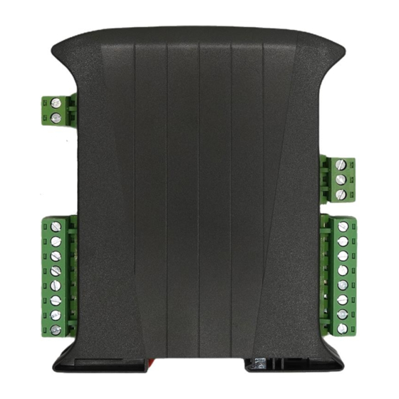
Summary of Contents for Synapse RTU-ADC8
- Page 1 RTU-ADC8 – 8 Channel Analogue In Modbus RTU Module Documentation Issue 1.4...
- Page 2 Features 8 Channels Each channel selectable as 4-20mA or 0-10V/0-2V DC operating mode (via internal “Push- On” jumper link settings) Software selectable per-channel 12/14/16/18bit resolution Software Modbus registers for Live Channel Reading Average Channel reading (software selectable as over 4/8/16 readings) Max channel reading* Min channel reading* Channel Resolution configuration setting...
-
Page 3: Safety And Esd Precautions
Safety and ESD Precautions Before first use, refer to this manual. Before first use, make sure that all cables are connected properly Please ensure proper working conditions, according to the device specifications e.g. Supply voltage, ambient temperature, maximum power consumption requirements. -
Page 4: Specifications
Specifications Voltage 6-28 VDC Power Supply Maximum Current 10mA @12V Max No of inputs Input Range (Voltage Mode) 0–10V / 0-2V Input Range (Current Mode) 0–20mA Analogue IO Resolution 12/14/16/18Bit Accuracy ±0.2% or better Operating Temperature -20°C to +70°C Environmental Conditions Storage Temperature -40°C to +85°C 0 .. - Page 5 RTU Module Pin Out 1 – 0V 2 – DC IN 3 – 0V 2 – RS485 B 1 – RS485 A 1 – CH7 + 8 – CH2 - 2 – CH7 - 7 – CH2 + 3 – CH8 + 6 –...
- Page 6 Status LEDs & Modbus ID Modbus Address ID Link Setting Status LEDs Bottom Green Power On Modbus Rx Modbus Tx Link No Address Setting Modbus Address +1 Modbus Address +2 Modbus Address +4 Modbus Address +8 Modbus Address +16 No Links Use factory defaults* * Factory Default setting : ...
- Page 7 Modbus Address ID Selection Link Addr * Invokes Factory Default setting: Address Id = 1 Baud Rate = 19200 8N1 All NVRAM values reset to zero (where applicable)
- Page 8 Current/Voltage Input Mode Selection To change a channels operational mode between 4-20mA Current Loop input or 0-10V Voltage Input a set of internal push-on jumper links must be adjusted Each channel may be set according to the link setting below, the factory default position is 4-20mA mode on all channels.
- Page 9 RS485 Bus Option Links Fit links below to enable the function shown 120Ω Termination Resistor RS485 Low Bus Pull RS485 High Bus Pull Important: Only one set of bus data line pulls should be active, either at the master side or on a single slave Important: Termination resistors should only be enabled at far ends of bus...
-
Page 10: Rs485 Bus Connection
RS485 Bus Connection High Bus Pull 120Ω Termination 120Ω Termination RS485 A/+ Modbus Master RS485 B/- Low Bus Pull Module Module Module RTU Plug RS485 Wiring Belden 9481 (120Ω Cable) Shield – Only connect on one end of cable! - Page 11 Current Loop & Voltage Input Connections Voltage Input Mode 0-10V Current Loop Mode Arrows show current flow direction Low side configuration is preferred and recommended High side configuration Low side configuration 0V +24V 0V +24V Sensor Sensor...
- Page 12 Modbus Registers – Readings Register Type Read/Wite Description 40001 32Bit IEEE754 Float Read Only ADC Channel 1 Live Reading (Big Endian) 40003 32Bit IEEE754 Float Read Only ADC Channel 2 Live Reading 40005 32Bit IEEE754 Float Read Only ADC Channel 3 Live Reading 40007 32Bit IEEE754 Float Read Only...
- Page 13 Note : Channel Maximum/Minimum registers record the peek value, i.e. the highest/lowest values seen by the ADC, each subsequent live reading is tested against this value with the register value being updated if the live reading exceeds the threshold value stored here. Writing a value to the Max/Min registers will set a new threshold value for testing against.
- Page 14 40073 - Rolling Average This sets the number of readings used for the rolling average, if dealing with noisy or rapidly fluctuating signals this filter will help to stabilise the reading. Register Value Setting 8 Readings 4 Readings 8 Readings 16 Readings 40074 - Modbus Baud Rate This sets the serial baud rate of the unit...
- Page 15 Decoding RAW ADC Modbus Readings The values stored by the RTU unit for Live/Average/Max/Min values are usually presented as 32Bit IEE754 Float, having an accuracy of 6 significant figures, if the ADC unit is configured to output the raw ADC readings greater accuracy can be obtained. To convert the raw readings to voltage/mA use the below process using the appropriate scaler depending on the ADC channel resolution setting.
-
Page 16: Software Support
Software Support Open-Source code samples can be downloaded from the GitHub repositories below : RTU Specific Configuration Tool https://github.com/synapsertu/rtu-ai8 Multi RTU module Logger https://github.com/synapsertu/rtu-log Modbus Utilities The following windows and Linux command line utilities are useful for development Windows/Linux x86 Binary https://www.modbusdriver.com/modpoll.html Raspberry Pi/Linux https://github.com/epsilonrt/mbpoll...


Need help?
Do you have a question about the RTU-ADC8 and is the answer not in the manual?
Questions and answers