Table of Contents
Advertisement
Quick Links
Instruction Manual
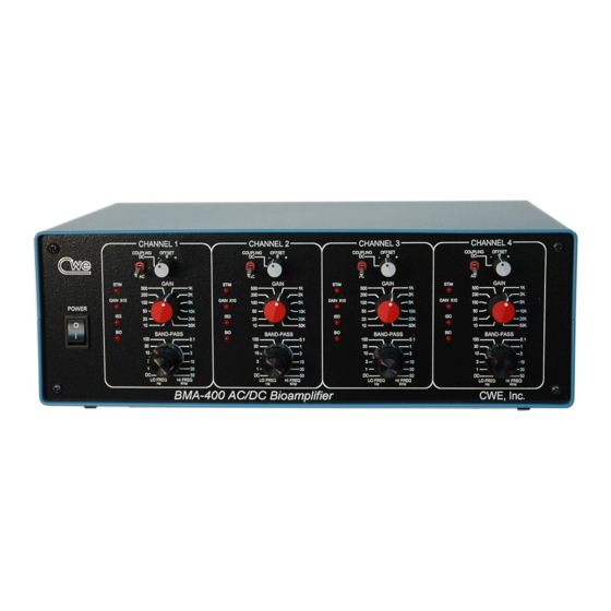
BMA-400
4-Channel Bioamplifier
Read instructions carefully before operating this device.
This device is not to be used for Human Life Support applications.
To avoid possible electrical shock, do not operate this device if is wet or has had liquids spilled onto it.
Service or calibration procedures should only be performed by qualified personnel familiar with the
electrical hazards of line-powered devices.
Ardmore PA 19003 U.S.A.
(610)642-7719
info@cwe-inc.com
©CWE 2023
www.cwe-inc.com
Advertisement
Table of Contents

Related Manuals for CWE BMA-400


Summary of Contents for CWE BMA-400
- Page 1 Instruction Manual BMA-400 4-Channel Bioamplifier Read instructions carefully before operating this device. This device is not to be used for Human Life Support applications. To avoid possible electrical shock, do not operate this device if is wet or has had liquids spilled onto it.
- Page 2 STATEMENT OF WARRANTY IF THIS INSTRUMENT FAILS WITHIN A PERIOD OF ONE YEAR FROM THE DATE OF DELIVERY OR INSTALLATION, CWE, INC. WILL, AT ITS OPTION, REPAIR OR REPLACE IT FREE OF CHARGE TO THE PURCHASER. THIS WARRANTY EXCLUDES DAMAGE INCURRED THROUGH ABUSE OR ACCIDENT AND CONSUMABLE ITEMS OR COMPONENTS SUCH AS BATTERIES.
-
Page 3: Table Of Contents
3.0 POWER SUPPLY CONNECTION ..................5 4.0 INPUTS ..........................6 4.1 INPUT CONNECTOR WIRING ................. 6 Figure 2: BMA-400 Input Connector Wiring ..............6 5.0 AMPLIFIER CONTROLS ....................7 Figure 3: Front panel controls (one channel shown) ............7 5.1 AC/DC COUPLING ....................7 5.2 GAIN CONTROL ....................... -
Page 4: Introduction
The BMA-400 Bioamplifier is a four-channel AC/DC preamplifier for the low-noise recording of muscle, nerve, or other biopotentials. The wide gain range of the BMA-400 allows its use as a primary amplifier whose output can be fed directly to data acquisition systems or oscilloscope displays. -
Page 5: Specifications
Weight ....................5 lbs. (2.3kg) 3.0 POWER SUPPLY CONNECTION included with the BMA-400 is a universal input device that can be used POWER SUPPLY with any mains voltage in the range 95 - 240VAC, 50 or 60Hz. It is only necessary to connect the appropriate power cord for your country. -
Page 6: Inputs
NOTE! For proper amplifier operation, all three input pins MUST be connected! COMMON - IN + IN -12V +12V BMA-400 Input Cable Plug (do not use pins 4 or 7) Figure 2: BMA-400 Input Connector Wiring © 2023 CWE, Inc. -
Page 7: Amplifier Controls
BMA-400 Instruction Manual 5.0 AMPLIFIER CONTROLS For most applications, it is only necessary to select appropriate GAIN BANDPASS FILTER settings. Other functions, such as stimulus passing through the recording electrodes, require use of the or other connections. AC coupling is normally used for... -
Page 8: Gain Control
+1-5V range. 5.3 FILTERS The band-pass filters contained in the BMA-400 are of the Butterworth type, for flattest response and minimum peaking. The slope of the filters is -12dB/octave. -
Page 9: Indicator Lights
BMA-400 Instruction Manual 5.4 INDICATOR LIGHTS The indicator lights show important information about the configuration of each channel. In normal operation with standard electrode connections, only the light will be lit. When head stages are in use, one or more of the other lights will indicate special functions. -
Page 10: Data Port Connector (Rear Panel)
BMA-400 Instruction Manual 8.0 DATA PORT CONNECTOR (REAR PANEL) connector on the rear panel provides access to the following functions: DATA PORT stimulus inputs (two per channel); stimulus control inputs (one per channel), and; additional output signals (one per channel). The required connector is a standard 25-pin D-SUB male plug. -
Page 11: Setting The Dc Offset Range
1.5mm DIN safety socket connections. 11.0 USING TRANSDUCERS WITH THE BMA-400 The BMA-400 has its supply voltages present on the input connector. The primary purpose of this feature is to power the optional head-stages described earlier. These voltages are +12V. -
Page 12: Ordering Information
2mm pin jack to 1.5mm DIN safety-socket plug, 5” (13cm) long (allows use 10-02051 PIN-DIN Adapter of PIN-PLUGS with ICA-400 cable and ISO-Z head-stage, set of 3 09-03200 BMA-400 PS 110/220V international power supply 09-03011 RACK-MOUNT Rack-mounting kit for BMA-400 © 2023 CWE, Inc.
Need help?
Do you have a question about the BMA-400 and is the answer not in the manual?
Questions and answers