Table of Contents
Advertisement
Quick Links
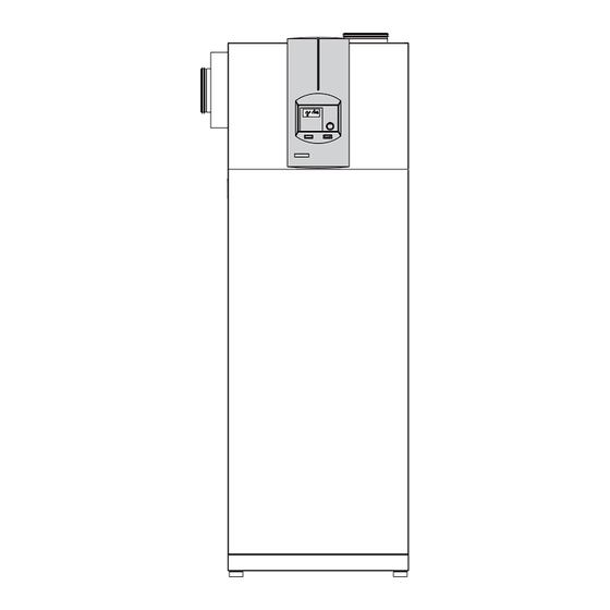
LWA 203, LWA 203 SOL, LWA 303, LWA 303 SOL
Central ventilation device with heat recovery
Operating and installation instructions
The installation (water and electrical work) and commissioning, as well as the maintenance of this equipment, must only be carried out by an
authorised qualified contractor in accordance with these instructions.
Technik zum Wohlfühlen
Index
1.
Operating instructions
for users and contractors
1.1
Equipment summary
1.2
Equipment description
1.3
Operating and installation instructions 2
1.4
Important information
1.5
Operation
1.6
Settings
1.7
FE 7 remote control
1.8
Maintenance and cleaning
1.9
What to do if ...?
2.
Installation instructions
for contractors
2.1
Equipment layout
2.2
Specification
2,3
Equipment description
2.4
Instructions and regulations
2.5
Installation
2.6
Commissioning
2.7
Maintenance and cleaning
2.8
LZM II commissioning summary
2.9
Adjustments (control level 3)
2.10 Troubleshooting
2.11 Commissioning list
Connection examples
4.
Environment/recycling
5.
Customer service/warranty
2
2
3
3
4
13
13
13
14
14
16
18
18
20
27
27
28
30
37
39
40 - 42
43
43
Advertisement
Table of Contents

Subscribe to Our Youtube Channel
Related Manuals for STIEBEL ELTRON LWA 203


Summary of Contents for STIEBEL ELTRON LWA 203
- Page 1 Technik zum Wohlfühlen LWA 203, LWA 203 SOL, LWA 303, LWA 303 SOL Central ventilation device with heat recovery Operating and installation instructions Index Operating instructions for users and contractors Equipment summary Equipment description Operating and installation instructions 2 Important information...
-
Page 2: Equipment Summary
1. Operating instructions for users and contractors 1.1 Equipment summary Display Rotary selector Rotary selector Reset / Auto Programming key Programming indicator Optical interface RS 232 Immersion heater push button Safety pressure limiter control indicator (see 1.9 "What to do if...?") System status display Mixer open Mixer close... -
Page 3: Operation
1.5 Operation 1.4 Important information Vital facts in brief Settings The operation is split over three control levels. During commissioning or after the heat-up Control levels 1 and 2 are accessible to users program has terminated, the LZM II display All settings follow the same pattern: and contractors alike. -
Page 4: Operating Modes (Control Level 1)
Display (including all elements) Heating times for DHW and central heating (black) 14-digit plain text display Day mode for heating circuit 1 Fan running Compressor running Switching time pairs for central heating and DHW operation Booster heater in operation Defrosting Setback mode for heating circuit 1 Emergency mode (booster heater) DHW mode... - Page 5 1.6.2 Overview of system parameters (control level 2) Select the required parameter with the rotary selector. For adjustments to parameters, turn to page 6. With system parameters ROOM TEMP 1 and ROOM TEMP 2 you can select the room temperature ROOM T HC1 for day and setback mode for heating circuits 1 and 2.
- Page 6 Settings at control level 2 for users and contractors Room temperature Ventilation DHW temperature With parameter ROOM TEMP 1 or 2, you can With parameter VENTILATION, you can adjust With parameter DHW TEMP, you can allocate adjust the Set room temperature for the day the operating modes for ventilation operation.
- Page 7 Time and date Holiday and party program YEAR STOP With parameter TIME/DATE, you can adjust the The holiday program controls heating, DHW time and the Summer time. and ventilation functions. When the outside At the factory, summer time is set to begin on temperature is above +4 °C, heating and DHW the 25 March and to end on the 25 October.
- Page 8 Heating curves Info temperatures In parameter HTG CURVES, you can adjust one The parameter INFO TEMP enables you to Heating curve respectively for heating circuit scan the ventilation equipment or ventilation 1 and 2. Selecting the correct heating curve is system Sensor temperatures, comparing set therefore vitally important.
- Page 9 Heating curve diagram One heating curve respectively can be adjusted for heating circuit 1 and heating circuit 2. At the factory, heating curve 0.6 is set up for heating circuit 1 and heating curve 0.2 for heating circuit 2. These heating curves relate to a set room temperature of 20 °C. °C Outside temperature Außentemperatur [°C]...
- Page 10 Heating programs BACK HEATING START In parameter HTG PROGS, you can adjust the heating programs for Heating circuit 1 and 2. You can adjust your heating system as follows: – for every day of the week (Monday, ..., Sunday) – Monday to Friday (Mo - Fr) HTG PROG –...
- Page 11 DHW and ventilation program DHW STOP In parameter DHW VENTILATION PROG, you can adjust the times for the day and setback temperatures for DHW heating or the Ventilation program. You can adjust the DHW heating or ventilation as follows: – for every day of the week DHW START (Monday, ..., Sunday) –...
-
Page 12: Standard Settings
Standard settings At the factory, the heat pump manager is programmed with the following standard settings: Switching times for heating circuit 1 and heating circuit 2 H1 / H2 (day mode) Monday - Friday 6:00 - 22:00 Saturday - Sunday 7:00 - 23:00 Room temperature 1 / 2 Room temperature in day mode... -
Page 13: Maintenance And Cleaning
1.7 FE 7 remote control 1.9 What to do if . . . ? opening the filter cassette. The LZM II contains a filter cleaning indicator that automatically reminds users every 3 . . . the fan symbol flashes on the months to clean the filters. -
Page 14: Installation Instructions
2. Installation instructions for contractors 2.1 Equipment layout Standard versions Extract connection DN 160 Evaporator Heating circuit pump Quick-acting air vent valve Solenoid valve (DHW) Electric booster (heating) Solenoid valve (heating) Expelled air connection DN 160 (optional) High pressure limiter 10 Fluid separator 11 Temperature sensor (defrosting) 12 Condenser - heating... - Page 15 SOL version Extract connection DN 160 Evaporator Heating circuit pump Quick-acting air vent valve Solenoid valve (DHW) Electric booster (heating) Solenoid valve (heating) Expelled air connection DN 160 (optional) High pressure limiter 10 Fluid separator 11 Temperature sensor (defrosting) 12 Condenser - heating 13 Compressor 14 Heat exchanger for solar DHW heating...
-
Page 16: Specification
2.2 Specification (The details listed on the type plate apply) LWA 203 LWA 203 SOL LWA 303 LWA 303 SOL Type Part no. 07 42 60 07 42 62 07 42 61 07 42 63 Dimensions H / W / D... - Page 17 Specification - control unit (LZM II) Supply voltage 230 V ~ ± 10 %, 50 Hz Power consumption Max. 8 VA EN 60529 Protection IP 1XB EN 60730 Class II Function type 1B Software - class A Control panel integration to DIN 43700 Cut-out 138 x 92 Clock backup, day >...
-
Page 18: Instructions And Regulations
2.3 Equipment description 2.3.1 Function diagram Extract fan Compressor Electric booster (heating) Condenser - heating Circulation pump Diverter valves Non-return valve Electric immersion heater (DHW) Heat exchanger/indirect coil 10 Condenser - DHW 11 DHW cylinder 12 Non-return valve 13 Common dryer 14 Evaporator 15 Expansion valve 16 Non-return valve... - Page 19 Fig. 6 Fig. 7 min. 500 Dimensions in mm Fig. 8...
-
Page 20: Installation
2.5 Installation Checking installation conditions 2.5.3 Heating water connection The room in which the equipment is to be installed must meet the following conditions: The heat pump must be installed by a 2.5.1 Transport and positioning qualified contractor in accordance with the ... - Page 21 Fitting the plug-in connector connecting the heat pump. Debris, such as Observe DIN 1988 and the regulations of your welding pearls, rust, sand, sealant, etc. can local water supply company. The plug-in connectors are equipped with a impair the operational reliability of the heat retainer with stainless steel serrations and pump, and can lead to the condenser being To protect against the risk of...
- Page 22 Pipe bends with union nuts and flat packing against condensation with a vapour-proof panel by approx. 10 degrees. are supplied with equipment with heat layer. – Remove the cover from the side panel. exchangers to enable an easy connection to The expelled air connector is located at the top –...
- Page 23 2.5,8 Sensor installation Remote control FE 7 PT 1000 collector sensor Connection array resistance values The temperature sensors have a decisive Resistance in Ω Temperature in °C influence on the function of your heating system. Therefore ensure the correct seating –...
- Page 24 2.5.9 Power connection Notify your local power supply company of the electrical connection. Only qualified electricians must carry out the installation in accordance with these instructions. Before any work, isolate the equipment from the power supply at the control panel. Route power supply and control cables/leads separately.
-
Page 25: Wiring Diagram
Wiring diagram Zentrales Lueftungsgeraet mit Waermepumpe und 3-stufiger 6,6 kW-Zusatzheizung 3/N/PE AC 50Hz 400V 1/N/PE AC 50Hz 230V L1 L2 L3 PE PE PE PE Residual heat sensor 230V-AC Restwaermefuehler Collector sensor (SOL) Kollektorfuehler (SOL) Outside temperature Aussenfuehler sensor Anlegefuehler Mischer Mixer contact sensor Remote control Fernbedienung... -
Page 26: System Configuration
2.6 Commissioning System configuration according to the Regular valve maintenance settings in the commissioning report. The Safety requires that valves are regularly commissioning report contains all settings for checked for perfect function. How quickly Only approved contractors may commission the control unit function. In case the system lime scale builds up depends on the local this equipment and instruct the owner in its operates incorrectly, initially check settings... - Page 27 Notes...
- Page 28 2.8 LZM II commissioning summary (control level 3) Parameter (shown in the display) COMMISSIONING ENTER CODE CHANGE CODE LANGUAGE GERMAN --------- MAGYAR BACK CONTRAST DISPLAY ACTUAL FLOW OUTSIDE TEMP ACTUAL DHW ACTUAL MIXER EMERGENCY MODE ON / OFF BACK SYSTEM TYPE SOLAR OPERTN MAX SOLAR TEMP SOLAR DIFFEREN...
- Page 29 DHW HYSTERESIS °C DEFROST EVAPORATOR TEMP BACK FLOW RATE SETBACK STANDARD PARTY BACK SUMMER VENT OFF MODE SETBACK MODE BACK FROST PROTECT OUTSIDE TEMP BACK NIGHT COOLING EXTRACT AIR SENS FE 7 BACK I PART HTG RES IDLE TIME COMPRESSOR BACK QUICK START RELAY TEST...
- Page 30 2.9 Adjustments Buffer E--SP2 EMERGENCY MODE In this case the mixer is used to raise the (control level 3) return temperature. With this constellation, the Characteristics in case of Fatal Error conditions mixer will regulate, independent of power- For an optimum and economical system in conjunction with emergency mode: OFF periods, as soon as the temperature in operation, it is not only the adjustments at...
- Page 31 direct comparison between the selected and PUMP CYCLES SUMMER OPRTN current outside temperature. Heating circuit pump control The SUMMER OPRTN parameter allows you Adjustment "1": Mild adjustment (averaging The PUMP CYCLES parameter only applies to to select the time when summer operation over a 24 h period) of the outside temperature, the direct heating circuit 1, i.e.
- Page 32 SET FIXED VALUE MIXER RESPTM SELECT FE Fixed value temperature Mixer runtime ⇒ setting range 60 to 240 The FE 7 remote control can be selected for The heat pump flow is regulated to a fixed both heating circuits and ventilation. This setting enables a matching of the mixer temperature.
-
Page 33: Room Influence
Room temperature-dependent return Room temperature control with weather- ROOM INFLUENCE temperature with weather compensation compensation With this type of control, a control cascade is This type of control offers two main Room influence for the FE 7 remote control formed from weather-compensated and room benefits:Incorrectly set heating curves are unit temperature-dependent return temperature... - Page 34 Standard settings: It is adjustable from 0 °C to + 12 °C; the connected DHC stages can be defined. – 5 °C with LWA 203 (SOL) standard setting is 5 °C. – 10 °C with LWA 303 (SOL) The standard setting is OFF, since all output The DHC stages are enabled for heating stages are connected at the factory.
- Page 35 For standard ventilation, select the intended For minimum ventilation, select the respective FLOW RATE flow rate. Where that is not available, a 0.4 to output magnitude (curve A or B). With LWZ 203 (SOL) ⇒ 125 m³/h = 4.0 V 0.5-fold air change is appropriate.
- Page 36 Example: After that, the heat pump and the associated SUMMER VENT heating circuit pump are switched ON. On the 17.02.06 at 14:50 h, the actual You terminate this function by pressing PRG temperature dropped below the minimum air This parameter can be set to OFF or ON. or by closing the control flap.
-
Page 37: Troubleshooting
Parameter 38 Fault list Checking and removing all faults in the fault list Fault Fault description Remedy EXTRACT AIR TEMP Actual temperature below the minimum extract air temperature Hold all living spaces, even during The heat pump will be switched OFF and the display will show EXTRACT TEMP MIN as absence, at a temperature of soon as the extract temperature is ≤... -
Page 38: Control Unit Reset
Additional parameters available for Fitted safety equipment Safety pressure limiter system analysis: The safety pressure limiter shuts down the In case of a fault, the safety equipment compressor, i.e. if the water flow rate is too Parameter 32 QUICK START: interrupts the relevant power circuit. - Page 39 ON / OFF DHW HYSTERESIS 1 °C to 10 °C 3 °C DEFROST – 10 °C to 3 °C – 5 °C LWA 203 – 10 °C LWA 303 FLOW RATE adjustable SUMMER VENT FROST PROTECT – 10 °C to 5 °C –...
-
Page 40: Connection Examples
Connection examples Legend Connection examples Ventilation equipment with heat pump Central heating circulation pump Heat pump condenser Electric booster Safety valve Expansion vessel DHW cylinder Heat exchanger (only for SOL versions) Non-return valve 10 Fill & drain valve 11 Circulation connection 12 Overflow valve 13 Mixing valve 14 Servomotor for mixing valve... - Page 41 Legend Connection examples Ventilation equipment with heat pump Central heating circulation pump Heat pump condenser Electric booster Safety valve Expansion vessel DHW cylinder Heat exchanger (only for SOL versions) Non-return valve 10 Fill & drain valve 11 Circulation connection 12 Overflow valve 13 Mixing valve 14 Servomotor for mixing valve 15 Solar collector...
- Page 42 Legend Connection examples Ventilation equipment with heat pump Central heating circulation pump Heat pump condenser Electric booster Safety valve Expansion vessel DHW cylinder Heat exchanger (only for SOL versions) Non-return valve 10 Fill & drain valve 11 Circulation connection 12 Overflow valve 13 Mixing valve 14 Servomotor for mixing valve 15 Solar collector...
-
Page 43: Environment And Recycling
Environment and Recy- cling Recycling of obselete appliances Appliances with this label must not be disposed off with the general waste. They must be collected separately and disposed off according to local regulations. Guarantee For guarantees please refer to the respec- tive terms and conditions of supply for your country. - Page 44 Tel. 0180 3 700705 | Fax 0180 3 702015 | info-center@stiebel-eltron.de Kundendienst STIEBEL ELTRON GmbH & Co. KG Tel. 0180 3 702020 | Fax 0180 3 702025 | kundendienst@stiebel-eltron.de Ersatzteilverkauf Tel. 0180 3 702030 | Fax 0180 3 702035 | ersatzteile@stiebel-eltron.de Dr.-Stiebel-Straße | D-37603 Holzminden...
Need help?
Do you have a question about the LWA 203 and is the answer not in the manual?
Questions and answers