
Related Manuals for Gigabyte R283-SF0-AAL1


Summary of Contents for Gigabyte R283-SF0-AAL1
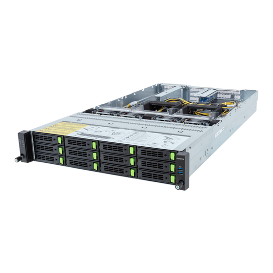
- Page 1 R283-SF0-AAL1 Rack Server 4th Gen Intel® Xeon® 2U DP 12-Bay Gen5 NVMe/SATA/SAS4 User Manual Rev. 1.0...
- Page 2 GIGABYTE's prior written permission. Documentation Classifications In order to assist in the use of this product, GIGABYTE provides the following types of documentation: User Manual: detailed information & steps about the installation, configuration and use of this product (e.g.
- Page 3 Conventions The following conventions are used in this user's guide: NOTE! Pieces of additional information related to the current topic. CAUTION! Precautionary measures to avoid possible hardware or software problems. WARNING! Alerts to any damage that might result from doing or not doing specific actions.
- Page 4 Server Warnings and Cautions Before installing a server, be sure that you understand the following warnings and cautions. WARNING! To reduce the risk of electric shock or damage to the equipment: • Do not disable the power cord grounding plug. The grounding plug is an important safety feature.
- Page 5 Electrostatic Discharge (ESD) CAUTION! ESD CAN DAMAGE DRIVES, BOARDS, AND OTHER PARTS. WE RECOMMEND THAT YOU PERFORM ALL PROCEDURES AT AN ESD WORKSTATION. IF ONE IS NOT AVAILABLE, PROVIDE SOME ESD PROTECTION BY WEARING AN ANTI-STATIC WRIST STRAP AT- TACHED TO CHASSIS GROUND -- ANY UNPAINTED METAL SURFACE -- ON YOUR SERVER WHEN HANDLING PARTS.
- Page 6 Installing or removing jumpers: A jumper is a small plastic encased conductor that slips over two jumper pins. Some jumpers have a small tab on top that can be gripped with fin-gertips or with a pair of fine needle nosed pliers. If the jumpers do not have such a tab, take care when us- ing needle nosed pliers to remove or install a jumper;...
-
Page 7: Table Of Contents
Table of Contents Chapter 1 Hardware Installation ................... 11 Installation Precautions .................. 11 Product Specifications ..................12 System Block Diagram ................... 16 Chapter 2 System Appearance ..................17 Front View ...................... 17 Rear View ....................... 18 Front Panel LEDs and Buttons ............... 19 RoT LEDs ....................... - Page 8 Chapter 5 BIOS Setup ....................50 The Main Menu ....................52 Advanced Menu ..................... 55 5-2-1 Trusted Computing ....................56 5-2-2 Serial Port Console Redirection ................57 5-2-3 SIO Configuration ....................60 5-2-4 PCI Subsystem Settings ..................61 5-2-5 USB Configuration ....................62 5-2-6 Network Stack Configuration ..................63 5-2-7 Post Report Configuration ..................64 5-2-8...
- Page 9 - 9 -...
- Page 10 This page intentionally left blank - 10 -...
-
Page 11: Chapter 1 Hardware Installation
Chapter 1 Hardware Installation Installation Precautions The motherboard/system contain numerous delicate electronic circuits and components which can become damaged as a result of electrostatic discharge (ESD). Prior to installation, carefully read the service guide and follow these procedures: • Prior to installation, do not remove or break motherboard S/N (Serial Number) sticker or warranty sticker provided by your dealer. -
Page 12: Product Specifications
Product Specifications NOTE: We reserve the right to make any changes to the product specifications and product-related information without prior notice. System Security Server Socket Operating Properties Š 2U Dimension Š 438 (W) x 87.5 (H) x 815(D) mm System fan Power Supply Š... - Page 13 Š Depends on SAS Add-on card RAID Š Intel® SATA RAID 0/1/10/5 Expansion Slot Riser Card CRS202P: 2 x PCIe x16 (Gen5 x16) FHFL slots, from CPU_0, for GPUs Š Riser Card CRS202Q: 1 x PCIe x16 (Gen5 x16) FHFL slot, from CPU_1, for GPUs Š...
- Page 14 Š The system power supply requires C19 power cord. System Š Aspeed® AST2600 management controller Management Š GIGABYTE Management Console (AMI MegaRAC SP-X) web interface Š Dashboard Š HTML5 KVM Š Sensor Monitor (Voltage, RPM, Temperature, CPU Status …etc.) Š Sensor Reading History Data Š...
- Page 15 cket Security Server Operating Properties Operating Operating temperature: 10°C to 30°C Š Operating humidity: 8%-80% (non-condensing) Properties Š System fan Power Supply Non-operating temperature: -40°C to 60°C Š Non-operating humidity: 20%-95% (non-condensing) Š Hardware Installation - 15 -...
-
Page 16: System Block Diagram
System Block Diagram NVMe x6 SATA x12 NVMe x6 12-bay 3.5"/2.5" Gen5 NVMe/SATA/SAS4 MCIO 8i x8 8-Channel DDR5, 16 x DIMMs PCIe5.0 x16 PCIe5.0 x16 PCIe5.0 x16 PCIe5.0 x16 8-Channel DDR5, 16 x DIMMs Speed up to 4800 MHz Speed up to 4800 MHz CPU0 CPU1 4 x UPI 16 GT/s... -
Page 17: Chapter 2 System Appearance
Chapter 2 System Appearance Front View HDD0 HDD3 HDD6 HDD9 HDD1 HDD4 HDD7 HDD10 HDD2 HDD5 HDD8 HDD11 Description Front Panel LEDs and Buttons USB 3.2 Gen1 Port x 2 Note! Drives with green latches support NVMe. • Refer to section 2-3 Front Panel LEDs and Buttons for a detailed description of the function of the LEDs. -
Page 18: Rear View
Rear View SLOT9 SLOT8 SLOT7 SLOT4 SLOT3 PSU2 PSU1 SLOT2 Description Description Mini DP Port USB 3.2 Gen1 Port x 2 ID LED OCP 3.0 Slot (Option/SFF) Server Management LAN Port PCIe Card Slot • Refer to section 2-5 Rear System LAN LEDs for a detailed description of the function of the LEDs. -
Page 19: Front Panel Leds And Buttons
Front Panel LEDs and Buttons No. Name Color Status Description Reset Button Press this button to reset the system. Press this button for the server to generate a NMI to the NMI button processor. If multiple-bit ECC errors occur, the server will effectively be halted. -
Page 20: Rot Leds
RoT LEDs ID LED Status LED LED on Front panel (Note5) ID LED Status LED EC Firmware (FW) Authentication fail or not exit EC FW is broken or not exit (Note1) Authenticating/Recovering BMC/BIOS Images Authenticating Images Blinks Blue Blinks Green Recovering BMC Active Flash 4 times per second 4 times per second... - Page 21 Active Flash Authentication (AUTH) Fail Blinks Blue Blinks Green BMC : AUTH Fail (Note2) 1 time per second 1 time per second Blinks Blue Blinks Amber BIOS : AUTH fail (Note2) 1 time per second 1 time per second Blinks Blue Blinks Green 2 times per second 2 times per second...
-
Page 22: Rear System Lan Leds
Rear System LAN LEDs Name Color Status Description Yellow 1 Gbps data rate 1GbE Speed Green 100 Mbps data rate 10 Mbps data rate Link between system and network or no access Green 1GbE Link / Blink Data transmission or reception is occurring. Activity LED No data transmission or reception is occurring. -
Page 23: Power Supply Unit Led
Power Supply Unit LED NOTE! The power supply may be vary based on the system configuration. PSU LED State Description No AC power to all power supplies 1Hz Green Blinking AC present / only standby on / Cold redundant mode 2Hz Green Blinking Power supply firmware updateing mode AC cord unplugged or AC power lost;... -
Page 24: Hard Disk Drive Leds
Hard Disk Drive LEDs 3.5” HDD LED #1 LED #2 HDD Present RAID SKU LED #1 Locate Rebuilding HDD Access Fault (No Access) Green ON(*1) BLINK (*2) Disk LED (LED on Back Panel) Amber No RAID configuration Removed HDD Green ON(*1) (via HBA) Slot (LED on... -
Page 25: Chapter 3 System Hardware Installation
Chapter 3 System Hardware Installation Pre-installation Instructions Computer components and electronic circuit boards can be damaged by discharges of static electricity. Working on computers that are still connected to a power supply can be extremely dangerous. Follow the simple guidelines below to avoid damage to your computer or injury to yourself. -
Page 26: Removing And Installing The Chassis Cover
Removing and Installing the Chassis Cover Before you remove or install the system cover • Make sure the system is not turned on or connected to AC power. Follow these instructions to remove the chassis cover: Remove the screw securing the chassis cover. Unlock the plastic handle and pull the grip handle to open the panel cover. -
Page 27: Removing And Installing The Hard Disk Drive
Removing and Installing the Hard Disk Drive Read the following guidelines before you begin to install the hard disk drive: • Take note of the HDD tray orientation before sliding it out. • The tray will not fit back into the bay if it is inserted incorrectly. •... - Page 28 Follow these instructions to install a 2.5" hard disk drive into 3.5" HDD Tray: Press the release button. Extend the locking lever. Pull the locking lever in the direction indicated to remove the HDD tray. Align the hard disk drive with the positioning screw on the HDD tray. Secure the hard disk drive with five screws.
-
Page 29: Removing And Installing The Fan Duct
Removing and Installing the Fan Duct Follow these instructions to remove the fan duct: Lift up to remove the fan duct. To reinstall the fan duct, align the fan duct with the guiding groove. Push down the fan duct until it is firmly seated on the system. -
Page 30: Removing And Installing The Heat Sink
Removing and Installing the Heat Sink Read the following guidelines before you begin to install the heat sink: • Always turn off the computer and unplug the power cord from the power outlet before installing the heat sink to prevent hardware damage. •... -
Page 31: Installing The Cpu And Heat Sink
Installing the CPU and Heat Sink Read the following guidelines before you begin to install the CPU: • Make sure that the motherboard supports the CPU. • Always turn off the computer and unplug the power cord from the power outlet before installing the CPU to prevent hardware damage. - Page 32 Carrier Types used for Package Types Package Type Xeon® SP XCC Xeon® SP MCC Xeon® SP+HBM Carrier Code NOTE! • The carrier code is marked on each carrier and matches a code laser marked on to the IHS(Integrated Heat Spreader) to ensure the right parts are used together. •...
-
Page 33: Removing And Installing Memory
Removing and Installing Memory Read the following guidelines before you begin to install the memory: • Make sure that the motherboard supports the memory. It is recommended that memory of the same capacity, brand, speed, and chips be used. • Always turn off the computer and unplug the power cord from the power outlet before installing the memory to prevent hardware damage. -
Page 34: Removing And Installing A Memory Module
3-6-2 Removing and Installing a Memory Module Before installing a memory module, make sure to turn off the computer and unplug the power cord from the power outlet to prevent damage to the memory module. Be sure to install DDR5 DIMMs on to this motherboard. -
Page 35: Processor And Memory Module Matrix Table
3-6-4 Processor and Memory Module Matrix Table Memory Q’ty CPU0 CPU1 for each CPU 1 DIMM 2 DIMM 4 DIMM 6 DIMM 8 DIMM 12 DIMM 16 DIMM System Hardware Installation - 35 -... -
Page 36: Removing And Installing The Pcie Card
Removing and Installing the PCIe Card • Voltages can be present within the server whenever an AC power source is connected. This voltage is present even when the main power switch is in the off position. Ensure that the system is powered off and all power sources have been disconnected from the server prior to installing a PCIe card. - Page 37 System Hardware Installation - 37 -...
-
Page 38: Installing The Mezzanine Card
Installing the Mezzanine Card 3-8-1 Installing the OCP 3.0 Mezzanine Card Use of the following type of OCP 3.0 NIC is recommended: • OCP 3.0 SFF with pull tab • OCP 3.0 SFF with ejector latch Follow these instructions to install an OCP 3.0 Mezzanine card: Remove the two screws securing the OCP 3.0 card slot cover. -
Page 39: Replacing The Fan Assembly
Replacing the Fan Assembly • Voltages can be present within the server whenever an AC power source is connected. This voltage is present even when the main power switch is in the off position. Ensure that the system is powered-down and all power sources have been disconnected from the server prior to replacing a system fan. -
Page 40: Removing And Installing The Power Supply
3-10 Removing and Installing the Power Supply Follow these instructions to replace the power supply: Flip up and then grasp the power supply handle. Press the retaining clip on the right side of the power supply unit in the direction indicated. Pull out the power supply unit using the handle. -
Page 41: Cable Routing
3-11 Cable Routing CPU1 CPU0 Motherboard: FP_1 Front IO Board: FP_1 Front Panel LEDs and Buttons Cable Front IO Board: FP_1 Motherboard: FUSB_1 Front Panel USB 3 Ports Cable System Hardware Installation - 41 -... - Page 42 CPU1 CPU0 Motherboard: BP_ATX1 HDD Backplane Board Power Cable Front HDD Board: ATX Motherboard: BP_1 HDD Backplane Board Signal Cable Front HDD Board: BP_1 System Hardware Installation - 42 -...
- Page 43 CPU1 CPU0 BP_1 Motherboard: SATA0 SATA Cable Front HDD Board: SLSAS0 Motherboard: SATA1 SATA Cable Front HDD Board: SLSAS1 Motherboard: SATA2 SATA Cable Front HDD Board: SLSAS2 System Hardware Installation - 43 -...
- Page 44 CPU1 CPU0 P2GP P2GP BP_1 Motherboard: Motherboard: U2_P0_3GE U2_P1_3GE NVMe 0-1 NVMe 6-7 Cable Cable Front HDD Board: Front HDD Board: A1: U.2 0/ A2: U.2 1 D1: U.2 6/ D2: U.2 7 Motherboard: Motherboard: U2_P0_4AC U2_P1_4AC NVMe 2-3 NVMe 8-9 Cable Cable Front HDD Board:...
- Page 45 CPU1 CPU0 Motherboard : GPU12V_S7 Riser Connector #3: -- Motherboard : GPU12V_S9 GPU Card Power Cable (Reserved) Riser Connector #2: -- Motherboard : GPU12V_S3 Riser Connector #1: -- System Hardware Installation - 45 -...
-
Page 46: Chapter 4 Motherboard Components
Chapter 4 Motherboard Components Motherboard Components BMC2 BIOS1 BIOS2 BMC1 34 35 CPU1 CPU0 Item Description 2 x 3 Pin ATX Power Connector 2 x 3 Pin ATX Power Connector 2 x 2 Pin P12V Backplane Power Connector 2 X 7 Pin ATX Power Connector MCIO Connector (U2_P1_4EG/4AC) 2 x 2 Pin P12V Backplane Power Connector 2 x 2 Pin P12V Backplane Power Connector... - Page 47 Item Description Front Panel Connector HDD Backplane Board Connector P12V GPU Power Connector (GPUP12V_S3) Riser Connector #1 (PCIe Gen5/x32 Slot) NCSI Connector for add-on LAN Card (NSCI_CNN) VGA Port Cable Connector Serial Port Cable Connector IPMB Connector OCP 3.0 Connector (PCIe Gen5 x16) System Battery Riser Connector #2 (PCIe Gen5/x32 Slot) Riser Connector #3 (PCIe Gen5/x16 Slot)
-
Page 48: Jumper Settings
Jumper Settings Enable Clear CMOS CLR_CMOS Default NCSI Switch NCSI_SW OCP 3.0 Slot NCSI Connector with Cable CPU1 CPU0 HSMB_SEL BIOS defined PMBUS_SEL BIOS defined Stop initial power on S3_MASK Normal [Default] when BMC is not ready Force Power On Force Power On Normal [Default] ME_UPDATE... -
Page 49: Backplane Board Storage Connector
Backplane Board Storage Connector 4-3-1 CBP20C7 Item Description MCIO Connector (MCIO 4i/U.2_0) MCIO Connector (MCIO 4i/U.2_1) MCIO Connector (MCIO 4i/U.2_2) MCIO Connector (MCIO 4i/U.2_3) MCIO Connector (MCIO 4i/U.2_4) MCIO Connector (MCIO 4i/U.2_5) MCIO Connector (MCIO 4i/U.2_6) MCIO Connector (MCIO 4i/U.2_7) MCIO Connector (MCIO 4i/U.2_8) MCIO Connector (MCIO 4i/U.2_9) MCIO Connector (MCIO 4i/U.2_10) -
Page 50: Chapter 5 Bios Setup
Chapter 5 BIOS Setup BIOS (Basic Input and Output System) records hardware parameters of the system in the EFI on the motherboard. Its major functions include conducting the Power-On Self-Test (POST) during system startup, saving system parameters, loading the operating system etc. The BIOS includes a BIOS Setup program that allows the user to modify basic system configuration settings or to activate certain system features. - Page 51 Main This setup page includes all the items of the standard compatible BIOS. Advanced This setup page includes all the items of AMI BIOS special enhanced features. (ex: Auto detect fan and temperature status, automatically configure hard disk parameters.) ...
-
Page 52: The Main Menu
The Main Menu Once you enter the BIOS Setup program, the Main Menu (as shown below) appears on the screen. Use arrow keys to move among the items and press <Enter> to accept or enter other sub-menu. Main Menu Help The on-screen description of a highlighted setup option is displayed on the bottom line of the Main Menu. - Page 53 Parameter Description BIOS Information Project Name Displays the project name information. Project Version Displays version number of the BIOS setup utility. Build Date and Time Displays the date and time when the BIOS setup utility was created. BMC Information (Note1) BMC Firmware Version Displays BMC firmware version information.
- Page 54 Parameter Description Memory Frequency Displays the frequency information of the installed memory. System Date Sets the date following the weekday-month-day-year format. System Time Sets the system time following the hour-minute-second format. BIOS Setup - 54 -...
-
Page 55: Advanced Menu
Advanced Menu The Advanced Menu displays submenu options for configuring the function of various hardware components. Select a submenu item, then press <Enter> to access the related submenu screen. BIOS Setup - 55 -... -
Page 56: Trusted Computing
5-2-1 Trusted Computing Parameter Description Configuration Enable/Disable BIOS support for security device. OS will not show security device. TCG EFI protocol and INT1A interface will not be TPM v1.2 Support available. Options available: Disable, Enable. Default setting is Enable. BIOS Setup - 56 -... -
Page 57: Serial Port Console Redirection
5-2-2 Serial Port Console Redirection Parameter Description Console redirection enables the users to manage the system from a COM1 Console remote location. Redirection (Note) Options available: Enabled, Disabled. Default setting is Disabled. Press [Enter] to configure advanced items. Please note that this item is configurable when COM1 Console Redirection is set to Enabled. - Page 58 Parameter Description Parity Š – A parity bit can be sent with the data bits to detect some transmission errors. – Even: parity bit is 0 if the num of 1's in the data bits is even. – Odd: parity bit is 0 if num of 1's in the data bits is odd. –...
- Page 59 Parameter Description Serial Port for Out-of-Band Management / Windows EMS console redirection allows the user to configure Console Redirection Emergency Management Settings to support Out-of-Band Serial Port management. Services (EMS) Console Options available: Enabled, Disabled. Default setting is Disabled. Redirection (Note) Press [Enter] to configure advanced items.
-
Page 60: Sio Configuration
5-2-3 SIO Configuration Description Parameter Displays the AMI SIO driver version information. AMI SIO Driver Version Super IO Chip Logical Device(s) Configuration Press [Enter] to configure advanced items. Use This Device Š – When set to Enabled allows you to configure the serial port settings. When set to Disabled, displays no configuration for the serial port. -
Page 61: Pci Subsystem Settings
5-2-4 PCI Subsystem Settings Parameter Description PCI Bus Driver Version Displays the PCI Bus Driver version information. When enabled, this setting will initialize the device expansion ROM SLOT# I/O ROM (Note) for the related PCI-E slot. Options available: Enabled, Disabled. Default setting is Enabled. SLOT# Lanes Change the PCIe lanes. -
Page 62: Usb Configuration
5-2-5 USB Configuration Parameter Description USB Configuration USB Devices: Displays the USB devices connected to the system. Enable/Disable the XHCI (USB 3.0) Hand-off support. XHCI Hand-off Options available: Enabled, Disabled. Default setting is Enabled. USB Mass Storage Driver Enable/Disable the USB Mass Storage Driver Support. Support Options available: Enabled, Disabled. -
Page 63: Network Stack Configuration
5-2-6 Network Stack Configuration Parameter Description Enable/Disable the UEFI network stack. Network Stack Options available: Enabled, Disabled. Default setting is Enabled. Enable/Disable the Ipv4 PXE feature. Ipv4 PXE Support Options available: Enabled, Disabled. Default setting is Enabled. Enable/Disable the Ipv4 HTTP feature. Ipv4 HTTP Support Options available: Enabled, Disabled. -
Page 64: Post Report Configuration
5-2-7 Post Report Configuration Parameter Description Post Report Configuration Error Message Report Enable/Disable the POST Error Message support. Post Error Message Options available: Enabled, Disabled. Default setting is Enabled. Halt On Options available: No Error, All Error. Default setting is No Error. BIOS Setup - 64 -... -
Page 65: Nvme Configuration
5-2-8 NVMe Configuration Parameter Description NVMe Configuration Displays the NVMe devices connected to the system. BIOS Setup - 65 -... -
Page 66: Chipset Configuration
5-2-9 Chipset Configuration Parameter Description Defines the power state to resume to after a system shutdown that is due to an interruption in AC power. When set to Last State, the system will return to the active power state prior to shutdown. When set to Restore on AC Power Loss (Note) Power Off, the system remains off after power shutdown. - Page 67 Parameter Description Enable/Disable the chassis intrusion alert function. Chassis Opened Warning Options available: Enabled, Disabled, Clear. Default setting is Disabled. BIOS Setup - 67 -...
-
Page 68: Tls Auth Configuration
5-2-10 Tls Auth Configuration Parameter Description Press [Enter] for configuration of advanced items. Enroll Cert Š – Press [Enter] to enroll a certificate • Enroll Cert Using File • Cert GUID Server CA Configuration Input digit character in 1111111-2222-3333-4444-1234567890ab format. –... -
Page 69: Iscsi Configuration
5-2-11 iSCSI Configuration Parameter Description Press [Enter] configure advanced items. Attempt Priority Š Attempt Priority – Use arrow keys to select the attempt, then press +/- keys to move the attempt up/down in the attempt order list. Commit Changes and Exit Š... -
Page 70: Chipset Menu
Chipset Menu Chipset Setup menu displays submenu options for configuring the function of Platform Controller Hub(PCH). Select a submenu item, then press <Enter> to access the related submenu screen. BIOS Setup - 70 -... - Page 71 5-3-1 Processor Configuration BIOS Setup - 71 -...
-
Page 72: Processor Configuration
Description Parameter Processor Configuration Press [Enter] to configure advanced items. CPU Socket 0/1 Configuration Š – Core Disable Bitmap(Hex) • Number of Cores to enable. 0 means all cores. FFFFFFF Pre-Socket Configuration means to disable all cores. The maximum value depends on the number of CPUs available. - Page 73 Description Parameter Enable/Disable memory encryption (TME). Memory Encryption (TME) (Note) Options available: Enabled, Disabled. Default setting is Disabled. Total Memory Encryption Options available: Enabled, Disabled. Default setting is Disabled. Multi-Tenant (TME-MT) Press [Enter] to configure advanced items. Provision S3M CFR Š...
-
Page 74: Common Refcode Configuration
5-3-2 Common RefCode Configuration Parameter Description Common RefCode Configuration Enable/Disable Non uniform Memory Access (NUMA). Numa Options available: Disable, Enable. Default setting is Enable. Divide physical NUMA nodes into evenly sized virtual NUMA nodes in ACPI table. This may improve Windows performance on CPUs Virtual Numa with more than 64 logical processors. -
Page 75: Upi Configuration
5-3-3 UPI Configuration Description Parameter Press [Enter] to configure advanced items. UPI Status Š – Press [Enter] to view the Uncore status. Link Frequency Select Š – Selects the UPI link frequency. – Options available: 12.8GT/s, 14.4GT/s, 16.0GT/s, Auto, Use Per Link Setting. - Page 76 Description Parameter MMIO High Granularity Size Š – Selects the allocation size used to assign mmioh resources. – Options available: 1G, 4G, 16G, 64G, 256G, 1024G. Default setting is UPI General Configuration 1024G. (continued) Limit CPU PA to 46 bits Š...
-
Page 77: Memory Configuration
5-3-4 Memory Configuration Description Parameter Integrated Memory Controller (iMC) When set to Enable, the system enforces Plan Of Record restrictions for DDR frequency programming. Enforce DDR Memory Frequency POR Options available: POR, Disable. Default setting is POR. Configures the maximum memory frequency. If Enforce POR is disabled, user will be able to run at higher frequencies than the Memory Frequency memory support (limited by processor support). - Page 78 Description Parameter Enable/Disable Assert ADR on S5. Assert ADR on S5 Options available: Enabled, Disabled. Default setting is Disabled. Auto is the detected SPD value and use it, otherwise use BIOS Build-in. Get Memory Timing Options available: Auto, BIOS Build-in. Default setting is BIOS Build-in. Press [Enter] to view memory topology with DIMM population Memory Topology information.
- Page 79 Description Parameter Leaky bucket time window based interface Hour Š – Leaky bucket time window based interface hour used for DDR (0-24). – Press the <+> / <-> keys to increase or decrease the desired values. Leaky bucket time window based interface Minute Š...
-
Page 80: Iio Configuration
5-3-5 IIO Configuration Description Parameter IIO Configuration Press [Enter] to configure advanced items. ® Intel VT for Directed I/O Š – Enable/Disable the Intel VT for Directed I/O (VT-d) support function by reporting the I/O device assignment to VMM through DMAR ACPI Tables. - Page 81 Description Parameter PCIe ACSCTL Š – Enable/Disable overwrite of PCI Access Control Services Control register in PCI root ports. – Options available: Disable, Enable. Default setting is Disable. Source Validation (Note) Š – Options available: Disabled, Enabled. Default setting is Disabled. ®...
-
Page 82: Advanced Power Management Configuration
5-3-6 Advanced Power Management Configuration Description Parameter Press [Enter] to configure advanced items. SpeedStep (Pstates) Š – Conventional Intel SpeedStep Technology switches both voltage and frequency in tandem between high and low levels in response to processor load. – Options available: Enable, Disable. Default setting is Enable. CPU P State Control Turbo Mode Š... - Page 83 Description Parameter Press [Enter] to configure advanced items. Enable Monitor MWAIT Š – Allows Monitor and MWAIT instructions. – Options available: Disable, Enable, Auto. Default setting is Auto. CPU C6 Report Š CPU C State Control – Enable/Disable CPU C6(ACPI C3) report to OS. –...
-
Page 84: Pch Configuration
5-3-7 PCH Configuration Description Parameter PCH-IO Configuration Press [Enter] to configure advanced items. SATA Configuration Š – Enable/Disable SATA controller. – Options available: Enabled, Disabled. Default setting is Enabled. SATA Mode Selection Š – Configures on chip SATA type. – AHCI Mode: When set to AHCI, the SATA controller enables its AHCI functionality. - Page 85 Description Parameter SATA Port 0/1/2/3/4/5/6/7 Š – Enable/Disable Port 0/1/2/3/4/5/6/7 device. – Options available: Enabled, Disabled. Default setting is Enabled. Hot Plug (for Port 0/1/2/3/4/5/6/7) SATA And RST Š – Enable/Disable HDD Hot-Plug function. Configuration/ – Options available: Enabled, Disabled. Default setting is Enabled. SATA Controller And RST Spin Up Device (for Port 0/1/2/3/4/5/6/7) Configuration (continued)
- Page 86 Description Parameter SATA Configuration Š – Enable/Disable SATA controller. – Options available: Enabled, Disabled. Default setting is Enabled. SATA Mode Selection Š – Configures on chip SATA type. – AHCI Mode: When set to AHCI, the SATA controller enables its AHCI functionality.
-
Page 87: Miscellaneous Configuration
5-3-8 Miscellaneous Configuration Description Parameter Miscellaneous Configuration Selects the active video type. Options available: Auto, Onboard Device, PCIE Device, Specific PCIE Active Video Device. Default setting is Auto. Enables Spread spectrum - only affects external clock generator. Options available: SSC Off, SSC = -0.3%, SSC = -0.5%, Hardware. External SSC - CK440 Default setting is SSC Off. -
Page 88: Server Me Configuration
5-3-9 Server ME Configuration Parameter Description General ME Configuration Oper. Firmware Version Displays the operational firmware version. ME Firmware Status #1/#2 Displays ME Firmware status information. Current State Displays ME Firmware current status information. Error Code Displays ME Firmware status error code. Recovery Cause Displays ME Firmware recovery cause. -
Page 89: Runtime Error Logging Settings
5-3-10 Runtime Error Logging Settings Description Parameter Runtime Error Logging Enable/Disable system error logging function. System Errors Options available: Enable, Disable. Default setting is Enable. Press [Enter] to configure advanced items. WHEA (Windows Hardware Error Architecture) Support Š Whea Settings –... - Page 90 Description Parameter Press [Enter] to configure advanced items. PCIE Error Š – Enable/Disable PCIE error. – Options available: Enable, Disable. Default setting is Disable. Uncorrected Error (Note) Š – Enables and escalates Uncorrectable/Recoverable Errors to error pins. – Options available: Enable, Disable. Default setting is Enable. Fatal Error Enable (Note) Š...
-
Page 91: Power Policy
5-3-11 Power Policy Description Parameter Selects a Power Policy Quick Setting. Options available: Standard, Best Performance, Energy Efficient. Default Power Policy Quick Settings setting is Standard. Conventional Intel SpeedStep Technology switches both voltage and frequency in tandem between high and low levels in response to processor SpeedStep (Pstates) load. - Page 92 Description Parameter Enables Logical processor (Software Method to Enable/Disable Logical Processor threads). Enable LP [Global] Options available: ALL LPs, Single LP. Default setting is ALL LPs. Options available: Enable, Disable. Default setting is Enable. Hardware Prefetcher Options available: Enable, Disable. Default setting is Enable. Adjacent Cache Prefetch Options available: Enable, Disable.
-
Page 93: Server Management Menu
Server Management Menu Parameter Description Enable/Disable FRB-2 timer (POST timer). FRB-2 Timer Options available: Enabled, Disabled. Default setting is Enabled. FRB-2 Timer Configures the FRB2 Timer timeout. The value is between 1 to 30 minutes. (Note1) timeout Default setting is 6 minutes. Configures the FRB2 Timer policy. - Page 94 Parameter Description System Event Log Press [Enter] to configure advanced items. View FRU Press [Enter] to view the FRU information. Information BMC VLAN Press [Enter] to configure advanced items. Configuration BMC network Press [Enter] to configure advanced items. Configuration IPv6 BMC Network Press [Enter] to configure advanced items.
-
Page 95: System Event Log
5-4-1 System Event Log Parameter Description Enabling / Disabling Options Change this item to enable or disable all features of System Event SEL Components Logging during boot. Options available: Enabled, Disabled. Default setting is Enabled. Erasing Settings Choose options for erasing SEL. Options available: No, Erase SEL Yes, On next reset,... -
Page 96: View Fru Information
5-4-2 View FRU Information The FRU page is a simple display page for basic system ID information, as well as System product information. Items on this window are non-configurable. (Note) The model name will vary depends on the product you purchased BIOS Setup - 96 -... -
Page 97: Bmc Vlan Configuration
5-4-3 BMC VLAN Configuration Description Parameter BMC VLAN Configuration Select to configure BMC VLAN ID. The valid range is from 0 to 4094. When BMC VLAN ID set to 0, BMC VLAN ID will be disabled. Select to configure BMC VLAN Priority. The valid range is from 0 to 7. BMC VLAN Priority When BMC VLAN ID is set to 0, BMC VLAN Priority will not be selected. -
Page 98: Bmc Network Configuration
5-4-4 BMC Network Configuration Parameter Description BMC network configuration Select NCSI and Dedicated Options available: Do Nothing, Model1(Dedicated), Model2(NCSI), Mode3(Failover). Default setting is Do Nothing. Lan Channel 1 Selects to configure LAN channel parameters statically or dynamically (DHCP). Configuration Address source Options available: Unspecified, Static, DynamicBmcDhcp. -
Page 99: Ipv6 Bmc Network Configuration
5-4-5 IPv6 BMC Network Configuration Parameter Description IPv6 BMC network configuration IPv6 BMC Lan Channel 1 Enable/Disable IPv6 BMC LAN channel function. When this item is disabled, the system will not modify any BMC network during BIOS IPv6 BMC Lan Option phase. -
Page 100: Security Menu
Security Menu The Security menu allows you to safeguard and protect the system from unauthorized use by setting up access passwords. There are two types of passwords that you can set: • Administrator Password Entering this password will allow the user to access and change all settings in the Setup Utility. •... -
Page 101: Secure Boot
5-5-1 Secure Boot The Secure Boot feature is applicable if supported by your Operating System. If your Operating System is not supporting Secure Boot, the system will hang when starting the Operating System. Parameter Description System Mode Displays if the system is in User mode or Setup mode. Enable/ Disable the Secure Boot function. - Page 102 Parameter Description Press [Enter] to configure advanced items. Please note that this item is configurable when Secure Boot Mode is set to Custom. Factory Key Provision Š – Allows to provision factory default Secure Boot keys when system is in Setup Mode.
- Page 103 Parameter Description Authorized TimeStamps (DBT) Š – Displays the current status of the Authorized TimeStamps Database. – Press [Enter] to configure a new DBT or load additional DBT from storage devices. Key Management – Options available: Update, Append. (continued) OsRecovery Signatures Š...
-
Page 104: Boot Menu
Boot Menu The Boot menu allows you to set the drive priority during system boot-up. BIOS setup will display an error message if the legacy drive(s) specified is not bootable. Parameter Description Boot Configuration Number of seconds to wait for setup activation key. 65535 (0xFFFF) Setup Prompt Timeout means indefinite waiting. - Page 105 Parameter Description FIXED BOOT ORDER Priorities Press [Enter] to configure the boot order priority. By default, the server searches for boot devices in the following sequence: Hard drive. Boot Option #1 / #2 / #3 / #4 / #5 CD-COM/DVD drive. USB device.
-
Page 106: Save & Exit Menu
Save & Exit Menu The Save & Exit menu displays the various options to quit from the BIOS setup. Highlight any of the exit options then press <Enter>. Parameter Description Save Options Saves changes made and closes the BIOS setup. Save and Exit Options available: Yes, No. - Page 107 Parameter Description Loads the default settings for all BIOS setup parameters. Setup Defaults are quite demanding in terms of resources consumption. If you are using low-speed memory chips or other kinds of low-performance components Restore Defaults and you choose to load these settings, the system might not function properly.
-
Page 108: Bios Recovery
BIOS Recovery The system has an embedded recovery technique. In the event that the BIOS becomes corrupt the boot block can be used to restore the BIOS to a working state. To restore your BIOS, please follow the instructions listed below: Recovery Instruction: 1. -
Page 109: Bios Post Beep Code (Ami Standard)
BIOS POST Beep code (AMI standard) 5-9-1 PEI Beep Codes # of Beeps Description Memory not Installed. Memory was installed twice (InstallPeiMemory routine in PEI Core called twice) Recovery started DXEIPL was not found DXE Core Firmware Volume was not found Recovery failed S3 Resume failed Reset PPI is not available...
Need help?
Do you have a question about the R283-SF0-AAL1 and is the answer not in the manual?
Questions and answers