Table of Contents
Advertisement
Quick Links
R283-S90-AAE1
R283-S90-AAE2
R283-S90-AAE3
R283-S90-AAJ1
R283-S90-AAJ2
R283-S90-AAJ3
4th Gen. Intel® Xeon® Scalable Server System - 2U DP 12+2-Bay NVMe/SATA/SAS (AAE1/AAJ1)
4th Gen. Intel® Xeon® Scalable Server System - 2U DP 12+2-Bay SATA/SAS (AAE2/AAJ2)
4th Gen. Intel® Xeon® Scalable Server System - 2U DP 12+2-Bay NVMe/SATA/SAS (AAE3/AAJ3)
User Manual
Rev. 1.0
Advertisement
Table of Contents

Related Manuals for Gigabyte R283-S90-AAJ1


Summarization of Contents
Hardware Installation
Installation Precautions
Safety and handling guidelines before installing hardware components.
Product Specifications
Detailed technical specifications of the server system components.
System Block Diagram
Visual representation of the server's internal architecture and connections.
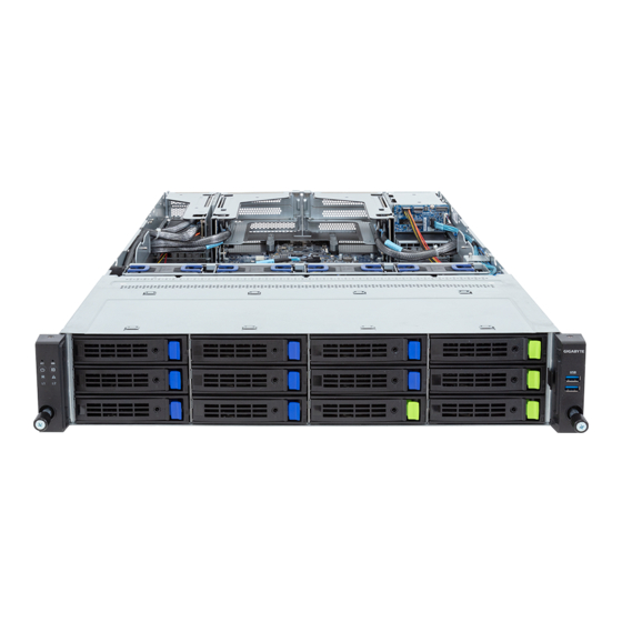
System Appearance
Front View
Identification of components and ports on the server's front panel.
Rear View
Identification of ports and slots on the server's rear panel.
Front Panel LEDs and Buttons
Description of front panel indicators and controls for system status.
RoT LEDs
Explanation of Root of Trust (RoT) related LED indicators and their meanings.
Rear System LAN LEDs
Description of status indicators for the server's rear LAN ports.
Power Supply Unit LED
Explanation of the LED status on the server's power supply unit.
Hard Disk Drive LEDs
Description of LED indicators for hard disk drive status and activity.
System Hardware Installation
Removing and Installing the Chassis Cover
Step-by-step guide for accessing the server's internal components.
Removing and Installing the Hard Disk Drive
Procedures for installing and removing HDDs in the server bays.
Removing and Installing the Fan Duct
Instructions for handling the server's internal fan duct assembly.
Removing and Installing the Heat Sink
Guide for safely removing and installing CPU heatsinks.
Installing the CPU and Heat Sink
Detailed steps for CPU and heatsink installation on the motherboard.
Removing and Installing Memory
Procedures for installing and removing DDR5 memory modules.
Removing and Installing the PCIe Card
Steps for adding or replacing PCIe expansion cards.
Installing the Mezzanine Card
Guide for installing OCP 3.0 mezzanine cards for networking.
Replacing the Fan Assembly
Instructions for replacing the server's fan assembly unit.
Removing and Installing the Power Supply
Procedure for replacing server power supply units.
Cable Routing
Diagrams showing proper cable management within the server chassis.
Motherboard Components
Motherboard Components
Identification and description of key components on the server motherboard.
Jumper Settings
Explanation of motherboard jumper configurations and their functions.
G-SC Module
Overview of the G-SC module and its connectors.
Backplane Board Storage Connector
Details on connectors for front and rear system storage boards.
BIOS Setup
The Main Menu
Introduction to the BIOS Setup program's main navigation screen.
Advanced Menu
Options for configuring advanced system hardware settings in BIOS.
Chipset Menu
BIOS settings related to the Platform Controller Hub (PCH) functionality.
Server Management Menu
BIOS options for server management features and BMC configuration.
Security Menu
BIOS settings for system access control and password protection.
Boot Menu
Configuration options for system boot device priority and behavior.
Save & Exit Menu
Options for saving BIOS changes or discarding them and exiting setup.
BIOS Recovery
Instructions for restoring the system's BIOS in case of corruption.
BIOS POST Beep code (AMI standard)
Codes indicating system status or errors during POST.
Need help?
Do you have a question about the R283-S90-AAJ1 and is the answer not in the manual?
Questions and answers