Table of Contents
Advertisement
Quick Links
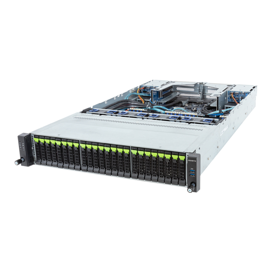
R283-S92-AAE1
R283-S92-AAE2
R283-S92-AAE3
R283-S92-AAE4
R283-S92-AAJ1
R283-S92-AAJ2
R283-S92-AAJ3
R283-S92-AAJ4
4th Gen. Intel® Xeon® Scalable Server System - 2U DP 24+4-Bay NVMe/SATA/SAS (AAE1/AAJ1)
4th Gen. Intel® Xeon® Scalable Server System - 2U DP 24+4-Bay NVMe/SATA/SAS (AAE2/AAJ2)
4th Gen. Intel® Xeon® Scalable Server System - 2U DP 24-Bay NVMe/SATA/SAS (AAE3/AAJ3)
4th Gen. Intel® Xeon® Scalable Server System - 2U DP 24+2-Bay NVMe/SATA/SAS (AAE4/AAJ4)
User Manual
Rev. 1.0
Advertisement
Table of Contents


Need help?
Do you have a question about the R283-S92-AAE1 and is the answer not in the manual?
Questions and answers