Sign In
Upload
Download
Table of Contents
Contents
Add to my manuals
Delete from my manuals
Share
URL of this page:
HTML Link:
Bookmark this page
Add
Manual will be automatically added to "My Manuals"
Print this page
×
Bookmark added
×
Added to my manuals
Manuals
Brands
Panasonic Manuals
Speaker System
SC-TMAX10PU
Service manual
Panasonic SC-TMAX10PU Service Manual
Wireless speaker system
Hide thumbs
1
Table Of Contents
2
3
4
5
6
7
8
9
10
11
12
13
14
15
16
17
18
19
20
21
22
23
24
25
26
27
28
29
30
31
page
of
31
Go
/
31
Contents
Table of Contents
Troubleshooting
Bookmarks
Table of Contents
Table of Contents
Safety Precautions
General Guidelines
Leakage Current Cold Check
Leakage Current Hot Check (See Figure 1.)
Protection Circuitry
Warning
Prevention of Electrostatic Discharge (ESD) to Electrostatically Sensitive (ES) Devices
Caution For Ac Cord (For
Service Caution Based On Legal Restrictions
Precaution Of Laser Diode
Static Electricity Protection Measures
Ground For Electrostatic Breakdown Prevention
Service Navigation
Service Information
Software Version Confirmation
Software Update
Specifications
Location of Controls and Components
Service Mode
Self-Diagnostic Mode
Self-Diagnostic Error Code Table
Sales Demonstration Lock Function
Troubleshooting Guide
No Power
Bluetooth® Pairing Failure
No Light From The Illuminator
No Sound
Check Points
Disassembly and Assembly Instructions
Disassembly Flow Chart
Types Of Screws
Main Component And P.C.b. Position
Disassembly Of Top Cabinet Unit
Disassembly Of Usb P.C.b. Unit
Disassembly Of Vfd P.C.b. Unit
And Key P.C.b. Unit
Disassembly Of Power P.C.b. Unit
Disassembly Of Main P.C.b. Unit
Disassembly Of Speakers
Disassembly Of CD Mecha
Voltage Measurement
Wiring Connection Diagram
Exploded View and Replacement Parts List
Cabinet Parts Location
Packing Parts & Accessories Section
Replacement Parts List
Advertisement
Quick Links
Download this manual
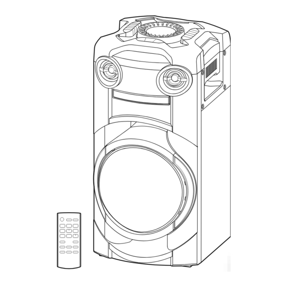
SC-TMAX10
Wireless Speaker System
offset printing
SC-TMAX10PU
Model No.
SC-TMAX10PR
SC-TMAX10E
Product Color: (K)...........Black Type
© Panasonic Corporation 2014
Unauthorized copying and distribution is a violation of law.
PSG1906006CE
2019
Table of
Contents
Previous
Page
Next
Page
1
2
3
4
5
Advertisement
Table of Contents
Need help?
Do you have a question about the SC-TMAX10PU and is the answer not in the manual?
Ask a question
Questions and answers
Related Manuals for Panasonic SC-TMAX10PU
Speaker System Panasonic SC-TMAX40 Operating Instructions Manual
Wireless speaker system (20 pages)
Speaker System Panasonic SC-TMAX45 Operating Instructions Manual
Wireless speaker system (64 pages)
Speaker System Panasonic SC-TMAX10E Service Manual
Wireless speaker system (31 pages)
Speaker System Panasonic SC-HD515 Operating Manual
Micro component (56 pages)
Speaker System Panasonic SC-HDX3 Operating Instructions Manual
Panasonic amplifier/speaker system operating instructions (12 pages)
Speaker System Panasonic SC-EH60 Operating Instructions Manual
System component (113 pages)
Speaker System Panasonic SC-MC07 Operating Instructions Manual
Compact speaker system (120 pages)
Speaker System Panasonic SC-NE1 User Manual
Wireless speaker system (16 pages)
Speaker System Panasonic SC-NE5 Owner's Manual
Wireless speaker system (32 pages)
Speaker System Panasonic SC-NE3 Operating Instructions Manual
Wireless speaker system (56 pages)
Speaker System Panasonic SC-CMAX5 Operating Instructions Manual
(60 pages)
Speaker System Panasonic SC-CMAX5 Owner's Manual
(22 pages)
Speaker System Panasonic SC-CMAX5 Operating Instructions Manual
(64 pages)
Speaker System Panasonic SC-UA7 Owner's Manual
Wireless speaker system (40 pages)
Speaker System Panasonic Sound Slayer SC-GN01 Owner's Manual
(21 pages)
Speaker System Panasonic SC-CMAX5GS Service Manual
(92 pages)
This manual is also suitable for:
Sc-tmax10pr
Sc-tmax10e
Table of Contents
Save PDF
Print
Rename the bookmark
Delete bookmark?
Delete from my manuals?
Login
Sign In
OR
Sign in with Facebook
Sign in with Google
Upload manual
Upload from disk
Upload from URL


Need help?
Do you have a question about the SC-TMAX10PU and is the answer not in the manual?
Questions and answers