
Related Manuals for paco SVDC1225


Summary of Contents for paco SVDC1225
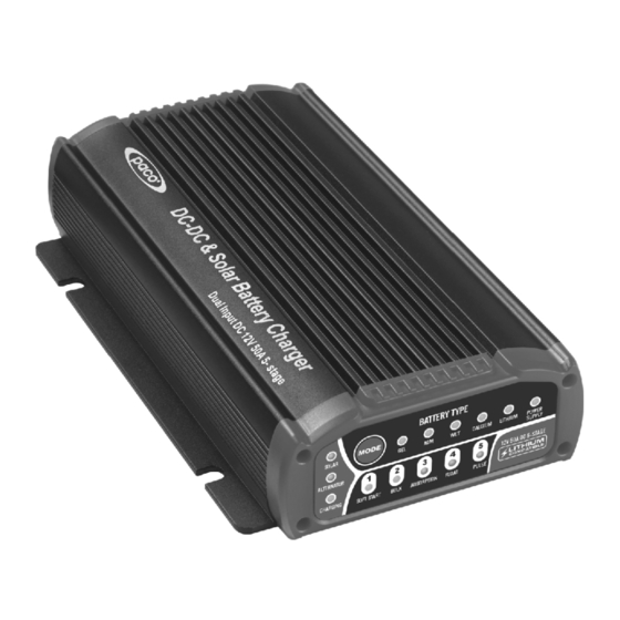
- Page 1 DC- DC & SOLAR BATTERY CHARGER Dual Input DC 25 Amp & 50Amp, 5 Stages Automatic Switchmode Instruction Manual Please read user manual carefully before use. P/No. SVDC1225, SVDC1225A, SVDC1250, SVDC1250A...
- Page 2 1. WARNINGS Use of an attachment not recommended or sold by the SVDC1225 / SVDC 1250 may result in a risk of fire, electric shock, or injury to persons. Explosive gases may escape from the battery during charging. Prevent flames and sparks and provide adequate ventilation.
- Page 3 The 5 stages are: Soft Start, Bulk, Absorption, Float and Pulse STEP 1 STEP 2 STEP 3 STEP 4 STEP 5 INCREASES MAIN CHARGING TOP CHARGE EQUALISATION FULLY CHARGED MAINTENANCE BATTERY YOUR VEHICLE (Calcium mode only) BATTERY CHARGING BATTERY LIFE BY IS CHARGED CAN BE STARTED Retums a full...
- Page 4 DUAL INPUT OPERATION The SVDC1225 / SVDC1250 Dual has 2 inputs. The Service battery will be charged from the alternator, solar panel, or both in combination. The solar panel adjusts itself to the Starter battery voltage. The Starter battery will be charged and maintained directly by the solar panel if the Service battery is fully charged.
-
Page 5: Protective Features
TEMPERATURE COMPENSATION The SVDC1225 / SVDC1250 is supplied with a 2 metre temperature sensor. The sensor monitors the battery temperature and adjusts (compensates) the charger's output to prevent overcharging. This is ideal for batteries used in warmer climates or environments. -
Page 6: Product Overview
5. PRODUCT OVERVIEW SVDC1225 SVDC1250 Power supply lamp Output Cable Stage lamp Ext. LED Cable Battery Type lamp Battery Mode Button Ignition Cable Solar in Cable Charging lamp Alt.in Cable Alternator lamp Ground Cable Solar lamp Temperature Sensor Cable Mounting Slots 4.5mm... - Page 7 SVDC1225A SVDC1250A SOLAR IN ALT IN OUTPUT Solar in (+) Cable Ground (-) Cable Power supply lamp Alt.in (+) Cable Stage lamp Ground (-) Cable Battery Type lamp Output (+) Cable Battery Mode Button Charging lamp Ground (-) Cable Anderson Plug (Optional) Alternator lamp Ignition Cable Solar lamp...
- Page 8 6.DLMENSIONS SVDC1225 SVDC1250 unit:mm...
-
Page 9: Technical Specifications
7. TECHNICAL SPECIFICATIONS Operating Conditions Charger model SVDC1225/SVDC1225A SVDC1250/SVDC1250A Solar Input Voltage Range 9-32Vdc Alternator Input Voltage Range 9-32Vdc Output Current Charger Model 50mA Input Current (No Load) Supply Model 80mA App.95% App.93% Efficiency Back Drain on Auxiliary Battery 35mA, +/-5%... - Page 10 25A up to 50A up to Bulk 14.1V (GEL) 14.1V (GEL) 14.4(AGM) 14.4(AGM) 14.7V(WET) 14.7V(WET) 15.4V(CALCIUM) 15.4V(CALCIUM) 14.4V(LITHIUM) 14.4V(LITHIUM) Constant voltage until Constant voltage until Absorption current drops to 3.8A current drops to 7.5A Float 13.7V Also with pulse feature (GEL, AGM, WET, CALCIUM) 13.6V Also with pulse feature (LITHIUM) 12.6V- 14.1V, 25-2.5A(GEL) 12.6V- 14.1V, 50-5A(GEL)
- Page 11 8. HOW TO READ LED DISPLAY BATTERY TYPE MODE SOLAR CALCIUM LITHIUM POWER SUPPLY ALTERNATOR 12V 50A DC 5-STAGE LITHIUM COMPATIBLE CHARGING SOFT START BULK ABSORPTION FLOAT PULSE LED Charge Indicators Solar Alternator Charging Stage lamp lamp lamp lamp lamp lamp lamp lamp...
-
Page 12: Fault Codes
9. FAULT CODES There are error codes that may be displayed. These will be displayed in the following way: Stage lamp lamp lamp lamp lamp lamp lamp lamp lamp Solar input high voltage Solar input reverse Alternator high voltage Alternator input reverse Output fault mode Calcium Lithium... -
Page 13: Installation
Electrical System Memory Protector be used. (2). Connect the Auxiliary Battery positive (+) terminal to the Output Cable (grey colour) from SVDC1225 / SVDC1250. Fit a 50A /100A fuse to the cable as close as possible to the Auxiliary Battery positive (+) terminal. - Page 14 (3). Connect the Auxiliary Battery negative (-) terminal to the SVDC1225 / SVDC 1250 Common Ground cable (black colour). Alternatively connect both Auxiliary Battery negative (-) terminals and SVDC1225 / SVDC1250 Common Ground cable to vehicle chassis ground. (4). Connect the Starter Battery positive (+) terminal to the SVDC1225 / SVDC 1250 Alternator Input cable (red colour).
- Page 15 Battery Chemistry LED you want is flashing. After you release the button, your selection is entered and saved. Your selection will be restored automatically even after the SVDC1225 / SVDC1250 is fully disconnected and reconnected. The default Battery Chemistry is AGM.
- Page 16 12.TYPICAL WIRING INSTALLATION (1).Full System Figure 1: SVDC1225 / SVDC1250 WARNING! Max 32V input Do not connect two solar panels in series Alternator/Starter Battery-Red (8mm2) Fuse Battery 1 (Starter Battery) For vehicles fitted with a Smart Alternator only Ground/Chassis output/Auxiliary Battery-Grey (8mm2)
- Page 17 Figure2:SVDC1225A / SVDC1250A WARNING! Max 32V input Do not connect two solar panels in series Anderson Plug (Optional) Fuse Battery 1 (Starter Battery) For vehicles fitted with a Smart Alternator only Anderson Plug (Optional) output/Auxiliary Battery-Grey (8mm2) Fuse Temperature Sensing-Black Temp Sensor mount (twin core) to battery casing...
- Page 18 (2). Alternator/Starter Battery Input Only Figure 3: SVDC1225 / SVDC1250 For vehicles fitted with a Smart Alternator only output/Auxiliary Battery-Grey (8mm2) Fuse Temperature Sensing-Black (twin core) Battery 2 (Aux Battery) Temp Sensor mount to battery casing Earth/Chassis Fuse LED Panel...
- Page 19 Figure4: SVDC1225A / SVDC1250A Anderson Plug (Optional) Fuse Battery 1 (Starter Battery) For vehicles fitted with a Smart Alternator only output/Auxiliary Battery-Grey (8mm2) Fuse Anderson Plug (Optional) Temperature Sensing-Black (twin core) Battery 2 (Aux Battery) Temp Sensor mount to battery casing LED Panel Mount Indicator Earth/Chassis...
- Page 20 (3).Solar Battery Input Only Figure 5: SVDC1225 / SVDC1250 LED Panel Mount Indicator Temperature Sensing-Black (twin core) Earth/Chassis output/Auxiliary Battery-Grey (8mm2) Fuse Temperature Sensing-Black (twin core) Battery 2 (Aux Battery) Earth/Chassis Temp Sensor mount to battery casing 12V Solar Panel...
- Page 21 Figure 6: SVDC1225A / SVDC1250A Anderson Plug (Optional) Fuse output/Auxiliary Battery-Grey (8mm2) Battery 2 (Aux Battery) Temp Sensor mount to battery casing Temperature Sensing-Black LED Panel (twin core) Mount Indicator External LED - Pink (1.5mm2) Earth/Chassis 12V Solar Panel...
-
Page 22: Frequently Asked Questions
Q. Is the SVDC1225/ SVDC1250 waterproof? A. The SVDC1225/ SVDC1250 is designed to be dust and waterproof. Normal use including river crossings and light engine washing will not pose any problem. Direct high pressure washing of the SVDC1225/ SVDC1250 unit or submersion for a period of time may cause some water damage and will not be covered under warranty. - Page 23 SAFETY The charger is designed for charging 12V lead-acid or lithium-ion batteries and provide power supply mode giving a constant voltage of 13.8V to provide power for appliances. Do not use the charger for any other purpose. Check the charger cables prior to use. Ensure that no cracks have occurred in the cables or in the bend protection.
- Page 24 CAUTION ALWAYS PLACE THE SVDC1225 / SVDC1250 IN AN ENVIRONMENT WHICH IS: A. WELL VENTILATED. B. NOT EXPOSED TO DIRECT SUNLIGHT OR HEAT SOURCE. C. OUT OF REACH FROM CHILDREN. D. AWAY FROM WATER / MOISTURE, OIL OR GREASE. E. AWAY FROM ANY FLAMMABLE SUBSTANCE.
Need help?
Do you have a question about the SVDC1225 and is the answer not in the manual?
Questions and answers