Table of Contents
Advertisement
Quick Links
Advertisement
Table of Contents

Related Manuals for Hydro Instruments 250 Series


Summary of Contents for Hydro Instruments 250 Series
- Page 1 Series 250 Amperometric Residual Chlorine Analyzer Instruction Manual The information contained in this manual was current at the time of printing. The most current versions of all Hydro Instruments manuals can be found on our website: www.hydroinstruments.com RPH-250 Rev. 1/11/2024...
-
Page 2: Table Of Contents
9. Disinfectant Sensor Lifespan ..............31 10. RPH-250 Circuit Boards ..............43 11. Monitor Internal Wiring and Connections ...........44 Tables: 1. Circuit Board Descriptions and Node Numbers .........35 2. Hydro Instruments RPH-250 Data Log File ........37 Drawings: Residual Chlorine Analyzer Parts Diagrams ........ 38-42... -
Page 3: Functions And Capabilities
I. FUNCTIONS AND CAPABILITIES 1. Basic Concept The RPH-250 residual analyzer is a multi-parameter instrument that can be used to measure a variety of disinfectants including: Free Chlorine, Total Chlorine, Chlorine Dioxide and Chlorite. Certain chemical species produce an electrical signal in the disinfectant sensor. The strength of this signal is a function of their concentration. - Page 4 3. Measurement The information provided in this document focuses on Free Chlorine and Total Chlorine measurement. Other disinfectant sensors are available and may have their own separate documentation. Free Chlorine: Free Chlorine is the sum of Hypochlorous Acid and Hypochlorite Ion. These two forms exist in equilibrium and their concentration depends on the pH and temperature of the sample water as shown in Figure 1.
- Page 5 4. Basic Specifi cations Power: 100-250 VAC, 50/60 Hz or 24 VDC, 10 W max. Inputs: (Qty.1) 4-20mA - PV1 for PID control (Qty.1) 4-20mA - Sample water pressure sensor (Optional) (Qty.1) Contact input - Sample water fl ow switch (Optional) Outputs: (Qty.4) Isolated 4-20 mA Digital Communication: Modbus RS-485 Relay Contacts: (Qty.4) SPDT, 10 Amps @ 120 VAC or 24 VDC, resistive load, 5 Amps @...
-
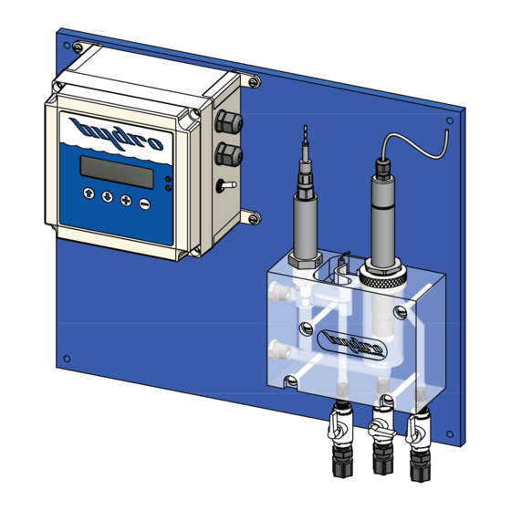
Page 6: Residual Analyzer Components
II. RESIDUAL ANALYZER COMPONENTS 1. Monitor The monitor provides the front end and back end interface for the entire residual analyzer. It features a 2-line x 20-character alphanumeric display. The residual, temperature and other readings are displayed here on the main operating screen. Navigating through the menus is done with the four push-buttons on the face of the monitor. - Page 7 Sample Water Flow Switch (Optional): The sample water fl ow switch is a separate accessory that can be installed into the sample water line at the inlet of the fl ow cell. It is used to indicate if sample water fl ow to the analyzer has stopped. It is a normally open contact that will close when water fl...
-
Page 8: Installation
III. INSTALLATION 1. Sample Water Connection and Control The residual analyzer requires a constant supply of sample water at a controlled rate and pressure. Flow: The sample water fl ow rate should be controlled at a rate appropriate for the fl ow cell being used. - Page 9 Consideration should be given to the sample point location with regards for use as a control signal for chemical injection. If there is a long time delay between chemical injection changes and the change being detected by the measurement cell, then chemical injection control is adversely aff...
- Page 10 FIGURE 4 - Sampling Examples Grab sample valve...
-
Page 11: Disinfectant Sensors
IV. DISINFECTANT SENSORS 1. Commissioning The Disinfectant Sensor Most disinfectant sensors use a membrane cap and are shipped with the membrane cap installed. The membrane cap must be removed and fi lled with electrolyte before use. For sensors that do not have a membrane cap such as the F3 type, these sensors have an electrolyte hull that is pre-fi... - Page 12 v. Hold the sensor vertically and thread the membrane cap on. Make sure to thread the membrane cap on completely. It will be tight against the sensor body. NOTE: Some electrolyte will be displaced out of the cap and through the vent hole. Use water to rinse off...
- Page 13 3. Cable Connections Grounding: Analyzers are supplied with a sample water ground pin to prevent electrical interferences that may be present in the sample water. The sample water ground pin is tied into the incoming AC ground. Disinfectant Sensors with mA Outputs: The disinfectant sensor is powered from the MB129 circuit board with an isolated 24VDC output, terminal (VO+).
-
Page 14: Ph Electrodes
V. PH ELECTRODES 1. Commissioning The pH Electrode The pH electrode is shipped in a cap containing a solution of pH buff er and potassium chloride. The electrode should only be removed from this solution when it is ready to be installed and used. -
Page 15: Calibration And Programming
VI. CALIBRATION AND PROGRAMMING 1. Modes of the RPH-250 Residual Analyzer a. Operation Mode: This is the mode used during normal operation of the RPH-250 Analyzer. It provides a display of the current residual reading, water temperature reading, pH and any alarm conditions that may exist. b. - Page 16 FIGURE 5 - Operation Menus (Operation Menu Flow Chart) (Control Type Dependent Operation Screens) Residual= 1.20PPM “Flow Pacing” AUTO “Flow Pacing” MANL Temp= 72F pH= 7.00 AUTO 24.9 % MANL 24.9 % This screen is only present AUTO > MANL > MANL >...
-
Page 17: Explanation Of Operation Screens
VII. EXPLANATION OF OPERATION SCREENS Main: This screen will display the residual value as well as the sample water temperature. If “Manual”, “Auto” or “Monitor” is selected as the “pH Compensation Mode”, the main screen will also display the pH value. Alarm Status: Displays any existing alarm conditions. - Page 18 FIGURE 6 - Confi guration Menus...
-
Page 19: Explanation Of Configuration Menus
VIII. EXPLANATION OF CONFIGURATION MENUS Main: The Confi guration Mode is structured as a “tree branch” program. The main screen is the trunk from which each branch can be accessed (Figure 6). Seven options appear on this screen, with one option blinking. To change which option is blinking, press the button. - Page 20 Calibration Type: The residual analyzer allows the user to select from four diff erent calibration methods including: (‘Sample’, ‘4.0 and 7.0’, ‘4.0 and 10.0’, ‘7.0 and 10.0’). The calibration type to use is completely up to the user. However Hydro Instruments recommends using the following selection criteria: ◦...
- Page 21 Notes to increase calibration accuracy: ◦ Before placing the pH electrode into a buff er for calibration, blot the bottom of the probe with a clean micro fi ber cloth. CAUTION: Take care not to scratch the probe surface as this will damage the probe and aff...
- Page 22 4. If the calibration point is accepted, an “accepted” screen will appear. Press down to clear the screen and the next buff er solution required will appear. 5. Place the pH electrode in the appropriate buff er solution and select ‘Begin’. 6.
- Page 23 ◦ AO# 20mA Cal: This screen allows for calibration of the AO# 20mA output. Using a meter to read the output, fi ne adjustments can be made using the buttons. Alarm: This branch accesses the settings for the four alarm relays. (Relay 1, Relay 2, Relay 3, Relay 4) •...
- Page 24 FIGURE 7 - PID Control Confi guration Menus Process Output Control Mode Residual Flow PID Setup: Control PID Setup: Control PID Setup: Control PID Setup: Control Resl Flow PO Resl Flow PO Resl Flow PO Resl Flow PO PO1 Units Control Type Residual Dead Band Flow Units...
- Page 25 FIGURE 8 - pH Calibration Menu Setup: Resl Temp pH Turbid Aout Alarm DL pH Low Alarm 6.00 pH High Alarm 9.00 AUTO pH Compensation Mode pH Compensation Mode MANUAL AUTO MANUAL MONITOR NONE Set Fixed pH 7.40 Sample Sample pH Calibration Type pH Calibration Type 4.0 and 7.0...
-
Page 26: Explanation Of Pid Control Menus
IX. EXPLANATION OF PID CONTROL MENUS Main: The PID Control Mode is structured as a “tree branch” program. The main screen is the trunk from which each branch can be accessed. Four options appear on this screen, with one option blinking. - Page 27 NOTE: In applications where fl ows vary, lag times may also change. In these instances, the use of the variable lag time settings will improve control timing. NOTE: If “Fixed” is selected as “Lag Time Method”, the settings of “Residual Max Lag Time” and “Flow at Variable Lag”...
- Page 28 • Gas Feed Type: Select either “CL2” or “SO2”. These two selections are basic classifi cations of what chemical type the PID Control program is controlling. “CL2” represents any chemical that will increase the residual reading and “SO2” represents and chemical that will decrease the residual reading.
-
Page 29: Maintenance & Cleaning
X. MAINTENANCE AND CLEANING The quality of the sample water greatly eff ects the frequency of maintenance and cleaning that is required. Maintenance and cleaning requirements will be diff erent for each installation. Visually checking the condition of the analyzer regularly and monitoring the disinfectant sensor signal are good ways to determine the required frequency of maintenance and cleaning. - Page 30 b. Membrane Cap For details on changing the membrane cap, refer to Section IV in this manual. IMPORTANT: If there is insuffi cient disinfectant (e.g. Chlorine) in the water for a long period of time, typically >24 hours, a biological fi lm can accumulate on the membrane. Should this occur, the membrane cap can no longer be used and must be replaced.
-
Page 31: Disinfectant Sensor Lifespan
FIGURE 9 - Disinfectant Sensor Lifespan... -
Page 32: Troubleshooting
XI. TROUBLESHOOTING Various factors can aff ect the disinfectant sensor. If irregularities occur, it may be useful to check the following: • Sample water pressure and fl ow rate • Sensor and electrode cables • Calibration • Chemical feed equipment •... - Page 33 0 – 5.0 mg/l and the actual application involves measuring for residuals of 0.1 or 0.2 mg/l, the accuracy of the measurement will suff er. If the normal measurement range is less than 25% of the ordered range, contact Hydro Instruments or an authorized distributor for guidance.
- Page 34 Ideally, the span calibration should be performed with a residual value of 50% or more of the ordered range. If the normal measurement range is less than 25% of the ordered range, contact Hydro Instruments or an authorized distributor for guidance. Temperature Temperature reading is not correct 1.
- Page 35 NOTE: The output calibration numbers from the factory calibration are recorded on the inside of the electronics enclosure for reference. Communication Errors • The MB220 Display board is communicating with the other boards by Modbus over the ribbon cable. If the ribbon cable is not properly connected to each board, then the MB220 Display board may lose communication with one or more circuit boards.
-
Page 36: Data Logger (Optional)
XII. DATA LOGGER (OPTIONAL) 1. Description: When enabled in the analyzer software, the data logger records the measured residual, sample water temperature, turbidity, and pH value (if being measured) at a selectable frequency. This data is recorded on the Micro SDHC memory card and can be retrieved using any text-reading program. - Page 37 Make your selection and then click “OK”. Now the data should have been imported into the Excel spreadsheet. TABLE 2: Hydro Instruments RPH-250 Data Log File Date Time...
- Page 38 MULTIPLE PROBE OPTIONS AVAILABLE. SEE SEPARATE DRAWING "RPH-PROBES" Date: 2022-12-09-v1 EXPLODED VIEW RESIDUAL CHLORINE ANALYZER Dwg. No.: RPH-OFC, EXP OPEN FLOW CELL...
- Page 39 Item Part Description Quantity pH Probe Cable PHE-14-S7 pH Electrode PHE-14-135 Vented pH Probe Gland PHV-GLAND-1 Port Plug, " NPT 850-007 Acrylic Flow Cell AFC-BODY Port Plug, " NPT 850-003 Ground pin assembly RPH-GND -20 x 3.25" RHMS (Stainless) Chlorine Probe (See drawing “RPH-250-PROBES”) Probe Nut PFC-PROBENUT O-Ring...
- Page 43 FIGURE 10 - RPH-250 Circuit Boards...
- Page 44 FIGURE 10 - Monitor Internal Wiring and Connections...
Need help?
Do you have a question about the 250 Series and is the answer not in the manual?
Questions and answers