Table of Contents
Advertisement
Quick Links
Advertisement
Table of Contents

Related Manuals for Hydro Instruments 210 Series


Summary of Contents for Hydro Instruments 210 Series
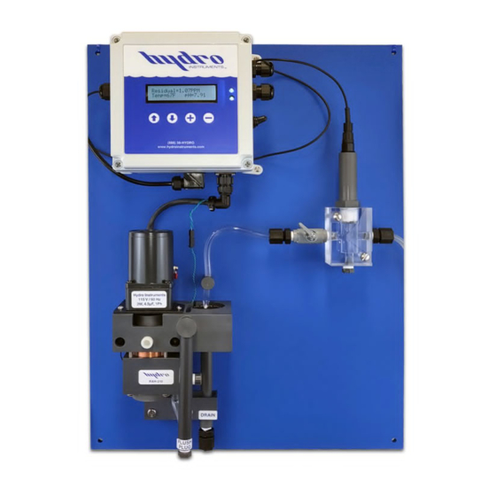
- Page 1 Series 210 Amperometric Residual Chlorine Analyzer Instruction Manual The information contained in this manual was current at the time of printing. The most current versions of all Hydro Instruments manuals can be found on our website: www.hydroinstruments.com RAH-210 Rev. 5/12/2021...
-
Page 2: Table Of Contents
Hydro Instruments Series 210 Amperometric Residual Chlorine Analyzer Table of Contents Functions and Capabilities ..............3 1. Basic Concept Description 2. Galvanic Cell Theory 3. Chlorine Chemistry 4. Measurement Chemistry 5. Basic Specifi cations System Component Description .............6 1. Measurement Cell 2. -
Page 3: Basic Concept Description
I. FUNCTIONS AND CAPABILITIES 1. Basic Concept Description: The Series 210 Residual Analyzer uses a Galvanic measurement cell consisting of a Cathode and a Copper Anode with the sample water as the electrolyte. This measurement method is referred to as Amperometric and has been in use for over 50 years. As described below, the measurement cell can be used to measure the concentration of Free Chlorine, Total Chlorine, Chlorine Dioxide and other oxidants. -
Page 4: Measurement Chemistry
Hypochlorous Acid is a weak acid that partially dissociates into a Hydrogen Ion and a Hypochlorite Ion as follows: ↔ HOCl + OCl – The degree of dissociation depends on the pH and the Temperature. Regardless of Temperature, below a pH of 5 the dissociation of HOCl remains virtually zero and above a pH of 10 the dissociation of HOCl is virtually 100%. -
Page 5: Basic Specifi Cations
Combined Chlorine Residual: ↔ O + 2NH Cl + 2KI 2KCl + I + 2NH OH + ½O ↔ O + NHCl + 2KI 2KCl + I + NH OH + ½O ↔ O + 2NCl + 6KI 6KCl + 3I + 2NH OH + 1.5O Second, the pH must be reduced to the range of 4.0 to 4.5 in order to prevent any dissociation of the... -
Page 6: System Component Description
II. SYSTEM COMPONENT DESCRIPTION Refer to Figure 2 for this section. 1. Measurement Cell: The measurement electrodes consist of a cathode and a Copper anode. The measurement electrodes are mounted in a PVC housing assembly. The electrodes are in the shape of concentric cylinders. -
Page 7: Installation
III. INSTALLATION Refer to Figure 3 for this section. 1. Sample Water Connection and Control: The following are some considerations relating to the sample water supply. The Series 210 Residual Chlorine Analyzer requires a constant supply of sample water at a controlled rate and pressure. Precautions should also be taken to ensure that the sample water reaching the measurement cell is not altered as it passes through the sample water piping. -
Page 8: Sample Water Piping Diagram
It should also be considered that the sample point should be located such that the residual reading can be used as a control signal for the chemical injection. Especially, it should be considered that if there is a long time delay between chemical injection changes and the change being detected by the measurement cell, then chemical injection control is adversely aff... -
Page 9: Sample Point Connection Diagram
FIGURE 4 (Sample Sources) FIGURE 5 (Installation Example) Water Flow Signal (4-20mA) Residual Signal (4-20mA) Residual Chlorine Analyzer RAH-210 Wall Panel Omni-Valve TRUE BLUE Vacuum Regulator NET #1 = 1234 NET #2 = 5678 TRUE BLUE Sample Water PRV RAH-PRV Ejector Vent Corporation Stop... -
Page 10: Setup, Reagents And Conditioning The Analyzer
IV. SETUP, REAGENTS, & CONDITIONING THE ANALYZER IMPORTANT NOTE: Prior to starting the analyzer, turn the striker with your thumb (from left to right) to be sure the motor turns freely. If the motor becomes stuck or is diffi cult to turn by hand, the problem must be identifi... -
Page 11: Conditioning The Analyzer
NOTE: Due to the nature of the potassium iodide (KI), the above solution will have a shelf life of approximately 15 days. This is because of the oxidation of the KI in solution. As this occurs, the solution will turn a golden color. Adding a drop of a reducing agent such as 0.02N sodium thiosulfate or 0.00564N phenylarsine oxide to the reagent can reverse the oxidation process. -
Page 12: Calibration And Programming
V. CALIBRATION AND PROGRAMMING 1. Modes of the RAH-210 Residual Analyzer a. Operation Mode (See Section VII): This is the mode used during normal operation of the RAH 210 Analyzer. It provides a display of the current residual reading, water temperature reading, pH and any alarm conditions that may exist. -
Page 13: Operation Menu Flow Chart
FIGURE 6 (Operation Menu Flow Chart) FIGURE 6.1 (Operation Menu Flow Chart) FIGURE 6.2 (Control Type Dependent Operation Screens) Residual= 1.20PPM “Flow Pacing” AUTO “Flow Pacing” MANL Temp= 72F pH= 7.00 AUTO 24.9 % MANL 24.9 % This screen is only present AUTO >... -
Page 14: Explanation Of Operation Mode Screens
VI. EXPLANATION OF OPERATION MODE SCREENS Main: This screen will display the residual value as well as the sample water temperature. If “Manual”, “Auto” or “Monitor” is selected as the “pH Compensation Mode”, the main screen will also display the pH value. -
Page 15: Confi Guration Menus From Password 250
FIGURE 7 (Confi guration Menus from Password 250) -
Page 16: Explanation Of Configuration Mode Screens
VII. EXPLANATION OF CONFIGURATION MODE SCREENS Main: The Confi guration Mode is structured as a “tree branch” program. The main screen is the trunk from which each branch can be accessed (fi gure 7 pg. 15). Seven options appear on this screen, with one option blinking. - Page 17 Calibration Type: The residual analyzer allows the user to select from four diff erent calibration methods including: 4-7 pH calibration, 7-10 pH calibration, 4-10 pH calibration, and the sample pH calibration. The calibration type to use is completely up to the user. However Hydro Instruments recommends using the following setting: A.
- Page 18 • Be aware of the temperature of the buff ers being used. Generally buff er manufactures write on their label at what temperature the pH is its true value (generally 77°F, 25°C). Temperature can infl uence dissociation and thus if your calibration is done with a buff er not at its prescribed temperature, your calibration will be inaccurate.
- Page 19 Residual: When “resl” is selected, the analog output will send a 4-20 analog signal representative of the residual value (4 mA being zero residual and 20 mA being full scale residual). PO1: When “PO1” is selected, the analog output will send a 4-20 analog signal representative of the PID Control Program Process Output (4 mA being zero and 20 mA being PO1 full scale).
-
Page 21: Pid Control Confi Guration Menus From Password 220
FIGURE 8 (PID Control Confi guration Menus from Password 220) Process Output Control Mode Residual Flow PID Setup: Control PID Setup: Control PID Setup: Control PID Setup: Control Resl Flow PO Resl Flow PO Resl Flow PO Resl Flow PO Control Type Residual Dead Band Flow Units... -
Page 22: Ph Calibration Menu Flow Chart
FIGURE 9 (pH Calibration Menu Flow Chart) Setup: Resl Temp pH Turbid Aout Alarm DL pH Low Alarm 6.00 pH High Alarm 9.00 AUTO pH Compensation Mode pH Compensation Mode MANUAL AUTO MANUAL MONITOR NONE Set Fixed pH 7.40 Sample Sample pH Calibration Type pH Calibration Type... -
Page 23: Explanation Of Pid Control Mode Screens
VIII. EXPLANATION OF PID CONTROL MODE SCREENS Main: The PID Control Mode is structured as a “tree branch” program. The main screen is the trunk from which each branch can be accessed. Four options appear on this screen, with one option blinking. To change which option is blinking, press the button. - Page 24 Flow: This branch accesses the settings for the proportional (fl ow) input. Flow Units: Select desired units (MGD, GPM, GPD, LPM, MLD, %, M /H). Flow Decimal Position: Select desired decimal position. Flow Full Scale: Enter the proportional input full scale. This setting should be what a 20 mA proportional input (AI1) signal represents.
-
Page 25: Maintenance & Cleaning
IX. MAINTENANCE AND CLEANING The quality of the water greatly eff ects the frequency of cleaning that is required. Cleaning requirements will be diff erent at each installation. Visually checking the condition of the analyzer regularly is the best way to determine the required frequency of cleaning. 1. -
Page 26: Cell Assembly
4. Cell Assembly: The analyzers cell assembly should be maintained on an as needed basis, but no less than once a year. NOTE: When removing the probe assembly, approximately 130 PTFE cleaning balls will fall out. Place a container underneath the cell assembly to catch the cleaning balls. CAUTION: Never reuse dirty and/or damaged cleaning balls. -
Page 27: Ph Probe
Failure of the pH probe will be indicated by an excessively high or low reading. If the probe cannot be recalibrated, then it must be replaced. Instructions for replacement will be included with the replacement pH probes available from Hydro Instruments. Refer to sections I.1, II.4, VI, and Troubleshooting of this manual. -
Page 28: Troubleshooting
50% or more of the ordered range. If the normal measurement range is less than 25% of the ordered range, contact Hydro Instruments or an authorized distributor for guidance on resetting the range of the analyzer. - Page 29 50% or more of the ordered range. If the normal measurement range is less than 25% of the ordered range, contact Hydro Instruments or an authorized distributor for guidance on resetting the range of the analyzer.
- Page 30 Reagent feeds too fast 1. This is caused by debris entering the star wheel assembly and becoming lodged between or damaging the critical surfaces. 2. Replace the star wheel assembly. Note that star wheel assemblies can be returned to Hydro Instruments for refurbishment.
- Page 31 Figure 9. 3. A blank display may indicate a failure of the display, the power supply board or the primary circuit board. Consult Hydro Instruments or an authorized representative for assistance. 4-20 mA Output channel values are not accurate 1. Verify the output selection is correct. For example, if the output signal on a 5 mg/l analyzer measuring 2.5 mg/l is something other than 12mA, verify that the output you are measuring is...
-
Page 32: Optional Data Logger
XI. OPTIONAL DATA LOGGER 1. Description: When enabled in the analyzer software, the data logger records the measured residual, sample water temperature, turbidity, and pH value (if being measured) at a selectable frequency. This data is recorded on the Micro SDHC memory card and can be retrieved using any text-reading program. -
Page 33: Hydro Instruments
Make your selection and then click “OK”. Now the data should have been imported into the Excel spreadsheet. TABLE 3: Hydro Instruments RAH-210 Residual Data Log File V5.1 Date... -
Page 34: Measurement Cell
MOTOR BLACK FRONT Date: August 2017 EXPLODED VIEW RESIDUAL CHLORINE ANALYZER Dwg. No. RAH-210-B-CELL, EXP MEASUREMENT CELL... -
Page 35: Residual Chlorine Analyzer Measurement Cell
Item Part Description Quantity 8-32 x ⁄ " Stainless Steel Bolt (RHMS) BTH-RA-169 Motor Assembly (115 VAC) RAH-1087-115 Motor Assembly (230 VAC) RAH-1087-230 Motor Plate RAH-108-1 Striker Assembly RAH-242 Top Body RAH-232 O-Ring OH-BUN-012 Front Plug RAH-833 ⁄ -20 x 2 ⁄... - Page 36 MOTOR BLACK FRONT Date: 2017-10-06-v1 EXPLODED VIEW RESIDUAL CHLORINE ANALYZER Dwg. No. RAH-210-CELL, EXP MEASUREMENT CELL...
- Page 37 Item Part Description Quantity 8-32 x ⁄ " Stainless Steel Bolt (RHMS) BTH-RA-169 Motor Assembly (115 VAC) RAH-1087-115 Motor Assembly (230 VAC) RAH-1087-230 Motor Plate RAH-108-1 Striker Assembly RAH-242 Top Body RAH-232 O-Ring OH-BUN-012 Front Plug RAH-833 ⁄ -20 x 2 ⁄...
- Page 38 Item Part Description Quantity pH Probe Cable PHE-14-S7 pH Electrode PHE-14-135 pH Probe Gland PHV-GLAND pH Fixure AFC-CHP-025 " x 1 " PVC Nipple 880-015 " Ball Valve 22321 Tubing Connector BKF-64 " PVC Plug 850-002 Date: 2020-07-02-v1 -20 x 2 "...
- Page 39 Item Part Description Quantity Reagent Bottle RAH-1300 ⁄ -20 x 1" Stainless Steel Screw (RHMS) BTH-RA-290 O-Ring (for Feeder Body) 3PS-332-NH3 Feeder Body RAH-459 ⁄ " NPT ⁄ " Tube Tubing Connector BKF-64 Tubing Guide RAH-460 Date: 2019-07-29-v1 ⁄ -20 x ⁄...
- Page 40 Buffer Feed Peristaltic Pump Assembly RAH-RFP Pumphead Assembly with Pump Tube, Hose Barbs, and Screws RAH-101-951 Neoprene Pump Tube with Hose Barbs RAH-TS-NOR ⁄ " LDPE Tubing P-114 ⁄ " NPT ⁄ " Tube Tubing Connector (PVDF Kynar) 10-4-4-KO NOTES: 1.
-
Page 41: Rah-210 Circuit Boards
FIGURE 10 (RAH-210 Circuit Board) -
Page 42: Monitor Internal Wiring And Connections
FIGURE 11 (Monitor Internal Wiring and Connections)
Need help?
Do you have a question about the 210 Series and is the answer not in the manual?
Questions and answers