Table of Contents
Advertisement
Quick Links
Document type
Document No.
Document No.
ECR/PCN
Version
TCN
A1.0
Distributed to
Archive method
Prepared
by
Date
7/19/2021
Confidential level: ★
Technical documents
H-1.601.00313
624- User Manual
Reference materials
Revise record
Change content
□
Production
Purchasing
department
department
□ Electronic documents
Reviewed
by
Date
Process code
Printing requirements
Explanation
New
Quality
department
Paper documents
ABMOBAN0003(A1.0)
624
□Colour
□Black and white
Prepared by
Jiying Wu
□
Marketing
R&D system
department
□ Others:
Approved
by
Date
Date of
approval
Advertisement
Table of Contents

Related Manuals for Amoul T6


Summary of Contents for Amoul T6
- Page 1 Confidential level: ★ ABMOBAN0003(A1.0) Document type Technical documents Process code Document No. H-1.601.00313 Printing requirements □Colour □Black and white 624- User Manual Reference materials Document No. Explanation Revise record ECR/PCN Date of Version Change content Prepared by approval A1.0 Jiying Wu □...
-
Page 2: Table Of Contents
2.6.2 Mainframe – right view ....................23 2.6.3 Mainframe - left view ....................24 2.6.4 T6 component diagram ....................25 2.6.5 3 Installation ..............................26 Packing items ........................26 Installation of battery ......................26 Connection of oxygen source ................... 27 Power supply connection .................... - Page 3 3.12 Patient breathe valve ......................35 3.12.1 Patient inspiratory valve ..................... 35 Patient expiratory valve....................35 3.12.2 4 Interface description ..........................37 Main interface components ....................37 Waveform interface ......................39 4.2.1 Monitor waveform switching ..................39 Loops interface ........................40 Monitoring value interface ....................
- Page 4 Alarm mode ......................... 61 Setting of alarm limits ......................62 6.10 Alarm parameter range ...................... 62 7 Operations ..............................64 Power-on ..........................64 Self-inspection and calibration ..................64 Select the patient ........................ 65 Ventilation type ........................67 Invasive ventilation ..................... 67 7.4.1 Non-invasive ventilation .....................
- Page 5 Accessories ........................100 11.14 Replacement of filter cotton .................... 100 11.15 Storage ..........................101 11.16 Disposal of abandoned device..................101 12 T6 accessories ............................. 102 13 Product specifications ......................... 103 13.1 Safety specifications......................103 13.2 Physical specifications ..................... 103 13.3 Environmental specifications ..................
- Page 6 Guidelines and manufacturer's statement - electromagnetic immunity ....115 14.4 Recommended isolation distance .................. 117 14.5 Patient physiological signal information of T6 .............. 118 14.6 Basic EMC performance of T6 ventilator ..............118 15 Product warranty..........................120 16 Classification description of toxic and harmful substances ............122...
- Page 7 Product information Thank you for purchasing the T6 ventilator. Before using the device, please read and understand contents of this Manual carefully, in order to use this instrument correctly. Please keep this Manual properly after reading and place it in an accessible location.
- Page 8 Intellectual property rights @2021 Ambulanc (Shenzhen) Tech. Co., Ltd., All rights reserved The intellectual property rights of this product and its operation manual belong to Ambulanc (Shenzhen) Tech. Co., Ltd., including but not limited to the patent right, trademark right, and copyright, etc. Ambulanc (Shenzhen) Tech.
- Page 9 Statement Ambulanc (Shenzhen) Tech. Co., Ltd. reserves the right to modify contents of this Manual without prior notice. Ambulanc (Shenzhen) Tech. Co., Ltd. reserves the right to change the technology without prior notice. Ambulanc (Shenzhen) Tech. Co., Ltd. reserves the right to modify the product specifications without prior notice.
- Page 10 Maintenance service Free service scope: • All devices in line with warranty service regulations of Ambulanc (Shenzhen) Tech. Co., Ltd. can enjoy free service. Charged service scope: • Any equipment beyond the scope of warranty service regulations of Ambulanc (Shenzhen) Tech. Co., Ltd. will be charged by Ambulanc for services; •...
- Page 11 E-mail: manager@ambu-lanc.com Return Return procedures Please follow the following steps if you do need to return the goods to Ambulanc (Shenzhen) Tech. Co., Ltd.: • Obtain the right of return: contact with after-sales service department of Ambulanc (Shenzhen) Tech. Co., Ltd. to inform serial number of Ambulanc product, which has been marked on the outer packing box.
- Page 12 treatment. 7. The doctors are responsible for the course of treatment. Ambulanc has no responsibility for the course of treatment. 8. Important data shall always be backed up to external storage media, such as clinical records, notebooks, etc. 9. Ambulanc shall not be held responsible for the loss of data stored in the system due to operator error or abnormal circumstances.
- Page 13 Blank page...
-
Page 14: Safety Instructions
• Follow the instructions in "9 Cleaning and Disinfection" to prevent infection or bacterial infection. • T6 shall only be used after you are subjected to medical training and technical instructions on ventilator as improper use can cause serious bodily injury. - Page 15 • When an external power supply is used to supply power for T6, ensure that the power cord does not form an obstruction. Please do not use the external power supply when it is not necessary (the battery power is less than 20% or the battery power is used uninterruptedly for a long time).
-
Page 16: Safe Use Of Oxygen
• Do not immerse T6 in any liquid. If any liquid gets into the cover, it can cause damage to the device. 1.2 Safe use of oxygen Warning: • An explosion will be caused when the high-pressure oxygen meets any combustibles (grease, oil, and alcohol, etc.). -
Page 17: Patient Ventilator Line Components
• Make sure that the patient breathing tube and inspiratory end are connected smoothly, otherwise the ventilation function of the equipment may be affected. • The ventilator shall not be placed next to a barrier as this will impede the flow of cold air and cause the device to overheat. -
Page 18: Battery
• Connect the external power supply of T6. Notices: [Maintaining of battery installation] In order to enable continuous operation of T6, it is recommended that a fully charged battery shall be installed at all times (even when an external power supply is connected to supply power). - Page 19 Battery capacity Oxygen inlet state Non-invasive Invasive Adult Pediatric Infant Patient trigger The product contains some harmful substances, so it can be safely used within the environment-friendly use period, but it shall be put into the recovery and circulation system after the environment-friendly use period.
-
Page 20: Overview
It is also suitable for all types of ambulance for emergency transport. The T6 may be operated only if it is securely mounted and fixed or placed on a licensed carrier platform. -
Page 21: Appearance Description
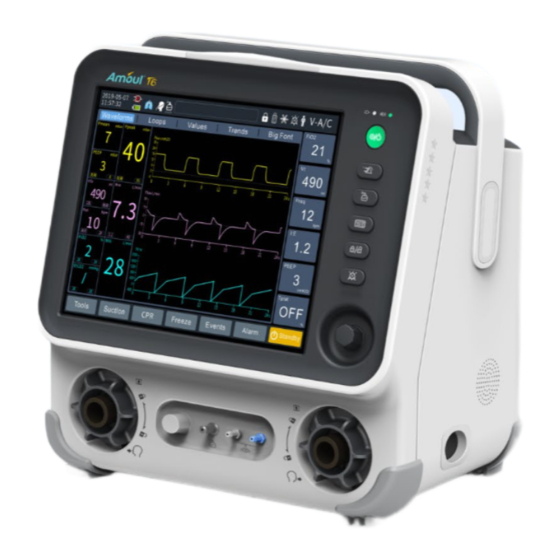
Ambulanc (Shenzhen) Tech. Co., Ltd. has designed all components required for the T6 ventilation system. 2.6 Appearance description 2.6.1 Mainframe - front view Fig. 1 Mainframe (front view) Components Description 1 Alarm light... - Page 22 works normally. 4 Battery sign It indicates the battery indicator. 5 Battery The indicator will flash during charging, and will be always indicator on when it is fully charged or during use. Tip: To indicate the ventilator is powered by an internal battery oran external power supply during operation.
-
Page 23: Mainframe - Rear View
14 External flow External flow sensor interface white tube. sensor interface 15 External flow External flow sensor interface blue tube. sensor interface 16 Nebulizer Used to connect the nebulizer. interface 17 Leak test Used to calibrate compliance plug 18 Inspiratory Used to connect the inspiratory line. -
Page 24: Mainframe - Right View
or connect to medical grade external equipments. 5 Network port Support connection to PC for software upgrade. 6 Hook Hook width: 45mm. 7 Gas supply Connect to high pressure gas supply port(high pressure) 8 Gas supply port(low Connect to low pressure gas supply. pressure) 9 Battery latch Used to remove and replace the rechargeable build-in... -
Page 25: Mainframe - Left View
2.6.4 Mainframe - left view Fig. 4 Mainframe (left view) Components Description 1 EtCO2 interface It is visible after lifting the silicone cover and is used to connect the ETCO2 module. 2 Oxygen source Used to connect the high-pressure oxygen source. interface (high pressure) 3 Oxygen source Used to connect the low-pressure oxygen source. -
Page 26: T6 Component Diagram
2.6.5 T6 component diagram Fig. 5 T6 component diagram Components Description 1 Support arm Used to support and suspend respiratory line of patients. Include the oxygen line, electronic system, mechanical 2 Mainframe structure, display, and carbon dioxide module. 3 Trolley Used to support the mainframe, support arm, oxygen cylinder and humidifier, etc. -
Page 27: Installation
After installation, you must carry out functional inspection (by referring to the "11 Maintenance and inspection") to ensure that the device works properly. 3.1 Packing items T6 ventilator is packed in a single box. Please refer to "12 T6 accessories" for packing items. 3.2 Installation of battery The battery used in T6 is a rechargeable lithium battery. -
Page 28: Connection Of Oxygen Source
3.3 Connection of oxygen source Fig. 7 Oxygen source interface The ventilator is provided two gas source interfaces, namely the high-pressure oxygen and low-pressure oxygen. When the ventilator is connected with the high-pressure oxygen gas source, the normal working gas source pressure is 300-600kPa. If pressure of gas source is lower than 300kPa, performance of the ventilator will be affected, or even the ventilation may be disenabled. -
Page 29: Power Supply Connection
interface shall be pressed, and then the gas source hose shall be pulled out. 3.4 Power supply connection The ventilator can be connected to DC power supply and AC power supply. 3.4.1 Connect AC power supply Fig. 8 AC power interface 1. -
Page 30: Install Support Arm
2. Tighten knob of the fixing block. 3.6 Patient respiratory line assembly and its connection Respiratory line assembly of T6 is divided into repetitive respiratory line assembly and disposable respiratory line assembly. And connection mode of the line is: double-line connection mode. Following steps shall be followed in the connection... - Page 31 Components Components 1 Expiratory branch filter 7 Humidifier 2 Expiratory line 8 Humidifier gas inlet 3 Flow sensor 9 Humidifier gas outlet 4 Simulated lung (patient) 10 Inspiratory line 5 Seeper trap in expiratory 11 Inspiratory branch filter branch 6 Seeper trap in inspiratory branch Notices: 1.
-
Page 32: Install Humidifier
3.7 Install humidifier Fig. 12 Humidifier installation diagram 1. Align humidifier pulley with the humidifier support mounting seat and slide into it, and then tighten the screws. 2. Install the filter to the inspiratory and expiratory interface. 3. Connect the filter in inspiratory branch to the humidifier inlet via the line. 4. -
Page 33: Infant Invasive Pipeline Connection
Infant invasive pipeline connection 图 3-8 Schematic diagram of infant invasive pipeline connection parts parts ①Infant flow sensor ②Expiratory line ③Humidifier... -
Page 34: Infant Noninvasive Pipeline Connection
Infant noninvasive pipeline connection 图 3-9 Schematic diagram of noninvasive pipeline connection for infants parts parts ①Infant nasal oxygen tube ② pressure pipeline tube ③Expiratory line ④Humidifier Warning: Infant patients: •You can only select CPAP, PCV mode or switch from CPAP, PCV mode to other modes during standby. -
Page 35: Install Etco2
Fig. 13 Nebulizer installation diagram Parts Parts 1 Nebulization port 2 Nebulization air-intake tube 3 Pneumatic nebulizer 3.11 Install EtCO2 Fig. 14 EtCO2 installation diagram Parts Parts 1 CO module port module 2 Mainstream CO2 monitoring 3 CO2 module adapter... -
Page 36: Patient Breathe Valve
3.12 Patient breathe valve 3.12.1 Patient inspiratory valve Fig. 15 Patient inspiratory valve Components Description 1 Safety valve cover Can be used to replace diaphragm of the safety valve. 2 Gas outlet Used to connect to patient inspiratory line, and is provided with a Φ15mm/22mm coaxial interface. - Page 37 2 Gas inlet Used to connect to patient expiratory line, and is provided with a Φ15mm/22mm coaxial interface. 3 PEEP valve disc Warning: The manufacturer, Ambulanc (Shenzhen) Tech. Co., Ltd., is not responsible for any performance problems caused by use of the respiratory line components provided by other manufacturers.
-
Page 38: Interface Description
4 Interface description 4.1 Main interface components Fig. 17 Main interface Components Description 1 System date and time Display current time and date. 2 Power supply service Display battery power and charging status. state 3 Adapter state Show whether the adapter is in place. 4 Patient trigger Indicate that current respiration is triggered by the patient... - Page 39 7 Alarm/hint message Display alarm and message hints. area 8 Screen lock Display locking status of screen 9 USB Display that the USB is connected now 10 Freezing mode Show the waveform freeze status. 11 Alarm mute prompt Display current alarm mute state. icon 12 Patient type icon Display current patient type (adult/Pediatric).
-
Page 40: Waveform Interface
enabled by the navigation knob, which will not be described below, but is considered to be available by default. 4.2 Waveform interface Select the [Waveform diagram] button on the main interface screen to open the interface as shown in the figure below Fig. -
Page 41: Loops Interface
Fig. 19 Waveform switching Notices: In the waveform interface, figureswitching interface, monitoring interface, trend diagram interface and large fonts interface,the waveforms or parameters to be switched can be switched by double click, which will not be descrbed in detail below. 4.3 Loops interface Select the [Loops] button on the main interface to open the interface as shown in the figure below. -
Page 42: Monitoring Value Interface
Fig. 20 Loops interface Monitoring value interface Select the [Monitoring value] on the main interface to open the interface as shown in the figure below Fig. 21 Monitoring value interface... -
Page 43: Trend Diagram Interface
4.5 Trend diagram interface In the main interface, select the [Trend diagram] option to pop up the trend setting interface. Enter the trend interface (as shown below). You can set up the trend diagram or view trend data and trend waveforms in this interface. -
Page 44: Freezing
Fig. 23 Big fonts interface 4.7 Freezing The freezing function is to temporarily stop real-time refresh of waveform and loops data on the screen, so as to review data of patient for a short period of time, and to observe condition of the patient during this period in detail. The data reviewed are the waveforms and loops 30 seconds before entering the freezing state. -
Page 45: Settings
black for others. The events can be viewed by category: display all, alarms, and events. • 4.9 Settings In the main menu, you can optimize settings of the mainframe to adapt to different usage situations. The main menu can be brought up by pressing the [Function menu] soft button on right side of the machine, and then corresponding settings can be made by the navigation knob or touching. - Page 46 Fig. 24 System settings Keys Description 1 Time setting Year, month, day, hour, minute 2 Language Chinese (default). Adjustable range: Chinese, English 3 Sound Type Beep(default) 4 Volume Level 1 by default. Adjustable level 1-3 5 Luminance Level 3 (default). Adjustable range: level 1-3 6 style Night (default).
-
Page 47: General
4.9.2 General Fig. 25 General setting Keys Description 1 Nebu time 1-90 min (adjustable) 2 Hold Time 1-40s (adjustable) 3 Sensor temperature 0-100 (adjustable) 4 Gas ATPD, STPD, BTPS (adjustable) 5 Humidifying Artificial nose and humidifier (optional) Indicate whether the oxygen concentration sensor 6 Oxygen sensor is connected 7 Height/weight... -
Page 48: Service
4.9.3 Service From [Settings]→[Service], you can enter the Service interface, which contains the user maintenance and manufacturer maintenance function. 1、For user maintenance function, in the standby interface, click [Settings] → [Service] → [User maintenance] (for the maintenance operation, please refer to 11 “Maintenance and inspection”): EtCO2 Zeroing (8.4 EtCO2 zeroing)... -
Page 49: Special Functions
5 Special functions 5.1 Lung recruitment Lung recruitment maneuver is a pulmonary protective ventilation strategy. The applying of a pressure higher than the normal mean airway pressure and maintaining it for a certain period of time during mechanical ventilation can enable reexpansion of more collapsed alveoli on one hand, and prevent secondary atelectasis caused by small tidal ventilation on the other hand. -
Page 50: Peepi
Fig. 26 CPR (select operation mode) Step 2: Start CPR by following the voice prompts and the "Dong Dong Dong..."beat 30:2: Namely, 30 pressings and 2 default ventilations are given 15:2: Namely, 15 pressings and 2 default ventilations are given ... -
Page 51: Nif
Manual breath, inspiratory hold, and expiratory hold functions cannot be initiated during PEEPi measurements. It's not available with HFNC, CPR and infant types. P0.1 P0.1 refers to the pressure drop within the first 100ms when the patient begins to breathe autonomously. -
Page 52: Sputum Suction
The dynamic lung state is as follows: Fig. 27 Dynamic lung 5.7 Sputum Suction Sputum suction is the process during which respirator is used to assist the user to suck sputum of the patient. The respirator automatically detects the action of the user disconnecting and connecting the patient's tube, applies oxygenated ventilation before and after sputum suction, and block relevant alarms during the process of sputum suction. -
Page 53: Inspiratory Holding
5.8 Inspiratory holding Inspiratory holding is the practice of artificially prolonging the patient's inspiratory stage and preventing the patient from expiration for a certain period of time. 1. After selecting the [Tools] key → [Hold] → [Inspiratory hold], and pressing the [Inspiratory hold] key continuously, the ventilator will enable the inspiratory holding function, and the system will prompt [Inspiratory holding is in progress]. -
Page 54: Manual
If apnea ventilation occurs, the Expiration Hold function is supported. 5.10 Manual After selecting [Tools] key → [Function] and clicking [Manual], the machine will automatically provide one inspiration or respiration in the current ventilation mode. Notices: Not available in HFNC and CPR mode ... -
Page 55: P-V Tool
5.12 P-V tool Mechanical ventilation set at optimal PEEP can improve oxygenation, improve alveolar mechanics, and reduce lung injury. The P-V tool is a method to determine the optimal PEEP by drawing a static pressure-volume curve (static P-V ring) and then identifying the characteristic points on the static P-V ring diagram curve. -
Page 56: Alarm
6 Alarm 6.1 Alarm message The alarm messages with the highest priority at present will be displayed in the alarm prompt bar on the main interface. If there are multiple alarms, you can click the alarm prompt message bar in the main interface, and the alarm message interface will be brought up to view other alarm messages (as shown below). -
Page 57: Technical Alarm
Type Voice alarm corresponding frequency: be heard, the pulse alarm texts+ will be 0.5s each interval is displayed!!! time. |0.1s|0.1s|0.5s|0.1s|, the duration of pulse is 0.2s, and the interval of pulse group is 7s. Medium-priori The alarm area on yellow 1. - Page 58 Alarm Alarm name Alarm description Priority code Motor temperature sensor 1010 Fault 1010! High failure 1011 Fault 1011! Motor temperature read failure High Oxygen supply pressure 1012 Fault 1012! High sensor failure Ambient pressure sensor 1 1013 Fault 1013! High failure Ambient pressure sensor 2 1014...
-
Page 59: Physiological Alarm
Alarm Alarm name Alarm description Priority code No valid patient flow rate No valid patient flow rate 1030 High measurement!!! measurement Patient side pressure Patient side pressure sensor 1031 High sensor failure!!! failure 1032 No pressure sensor!!! No pressure sensor High Input gas temperature Input gas temperature greater... -
Page 60: Battery Alarms
Alarm code Alarm name Alarm description Priority Minute ventilation volume Minute volume is below 2003 High is too low!!! lower limit Oxygen concentration is Oxygen concentration is 2004 High too high!!! above upper limit Oxygen concentration is 2005 Low Oxygen!!! High below lower limit 2006... -
Page 61: Communication Alarms
Mediu 1049 Low battery!!! Battery life time ≤ 20 minutes About to shut down, so 1050 connect to external power Battery life time ≤ 5 minutes High supply!!! High temperature during High battery temperature, battery discharge, and the 1051 and the system is about to High system is about to shut down. -
Page 62: Alarm Mode
Condition Horn alarm interface. Only the alarm The yellow light If it is a beep messages with the flashes, flash alarm, it will be Multiple highest priority will be frequency: 2s given with medium-priorit displayed in the each time medium priority in y alarms are prompt area;... -
Page 63: Setting Of Alarm Limits
Adjustment of alarm volume: Press the [Function menu] soft key, and click [System] → [Volume] to adjust the sound volume from :close , Level 1-3 . Alarm form: Press the [Function menu] soft key, and click [System] →[Sound Type] to ... - Page 64 Alarm parameter Alarm range Lower limit of minute 0.01L/min~25L/min ventilation Upper limit of oxygen 19%~100% concentration Lower limit of oxygen 18%~99% concentration Upper limit of positive end 1cmH2O-50 cmH2O expiratory pressure Lower limit of positive end Closed, 1cmH2O-40 cmH2O expiratory pressure Upper limit of airway pressure 12cmH O~100 cmH Lower limit of airway pressure Closed, 1cmH...
-
Page 65: Operations
7.1 Power-on Plug the power cord into power outlet. Make sure the external power indicator is Press the [ON/OFF] button to turn on T6. At this time, a progress bar indicating that the ventilator is subjected to self-inspection will appear on the screen. After the self-inspection, the main interface will pop up. -
Page 66: Select The Patient
Fig. 29 Startup calibration interface System calibration includes: Gas line zero calibration Line resistance calibration Line compliance calibration Flow sensor calibration Notices: The automatic self-inspection function is not intended as a substitute for function inspection. When using the machine, function inspection of the machine shall be carried out according to the contents described in "10 Maintenance and inspection". - Page 67 ventilation]. Fig. 30 Patient type selection Fig. 31 Patient setting Notices: Each time the patient type is switched, the system must be calibrated before ventilation can be initiated. If the previous patient ventilation is selected, the machine will use the previous ...
-
Page 68: Ventilation Type
7.4 Ventilation type This ventilator has two ventilation types: invasive ventilation and non-invasive ventilation. Notices: Setting of alarm limits shall be checked when switching from noninvasive to invasive ventilation. 7.4.1 Invasive ventilation Invasive ventilation is the ventilation of the patient through connection of artificial airway (endotracheal intubation and tracheotomy). -
Page 69: Set Ventilation Control Parameters
Fig. 32 Ventilation mode selection Set ventilation control parameters 7.6.1 Ventilation parameter setting After selecting the ventilation mode button in upper right corner of the interface in ventilation mode setting area, and the menu that is openeddisplays the ventilation parameters that can be set in this ventilation mode. 1. -
Page 70: Ventilation Parameters In Each Mode
3. Press the main control knob again to confirm the setting, or select [√] to confirm and save, or [×] to cancel the operation. 4. Follow the same method to set other parameters that need to be set. Fig. 33 Ventilation parameter setting 7.6.2 Ventilation parameters in each mode Ventilation mode Set parameters... - Page 71 time/breath rate/PEEP/oxygen concentration/sigh/inspiratory trigger mode/inspiratory trigger threshold/upper pressure limit/sigh Inspiratory pressure/inspiratory time/pressure rise time/SIMV frequency/PEEP/oxygen concentration/sigh/inspiratory trigger mode/inspiratory P-SIMV trigger threshold/expiratory switching sensitivity/trigger window/support pressure/upper pressure limit/sigh Support pressure/inspiratory trigger mode/inspiratory trigger threshold/expiratory switching sensitivity/PEEP/oxygen APRV concentration/low pressure time/high pressure time/high airway pressure/upper pressure limit/sigh Support pressure/inspiratory trigger mode/inspiratory trigger threshold/expiratory switching sensitivity/PEEP/oxygen...
-
Page 72: Ippv And Pcv
Oxygen therapy flow/oxygen concentration/upper pressure HFNC limit 7.6.3 IPPV and PCV Intermittent positive pressure ventilation: IPPV • During mechanical ventilation of IPPV (Intermittent Positive Pressure Ventilation), the ventilator always provides intermittent positive pressure ventilation. The pressure rises and is positive during inspiration, and the pressure returns to the baseline pressure during expiration. -
Page 73: V-A/C And P-A/C
ventilation/flow ratio imbalance caused by ARDS or COPD. Even when the respiratory line leaks, it can also ensure the supply of tidal volume. PCV shall be used when the gas line leaks. Typical pressure waveform of PCV is as follows: Fig. -
Page 74: V-Simv And P-Simv
Fig. 37 P-A/C typical pressure waveform The [Sigh] is a deep inspiration greater than current tidal volume/pressure at every other set ventilation times on the basis of the specified ventilation frequency, and is applicable for the patients who need mechanical ventilation for a long time. 7.6.5 V-SIMV and P-SIMV Synchronized intermittent mandatory ventilation: SIMV SIMV (Synchronized Interruptive Mandatory Ventilation) is a ventilation technology... -
Page 75: Cpap/Psv
SIMV cycle SIMV cycle Pressure Trigger window Trigger Trigger window Volume control Volume control Support pressure Inspiratory trigger Time Fig. 38 V-SIMV typical pressure waveform P-SIMV (pressure-limited synchronized intermittent mandatory ventilation) refers that the machine provides support pressure if the patient is able to trigger the ventilator outside the trigger window during mechanical ventilation. -
Page 76: Bippv
rate of positive airway pressure over time in order to maintain a constant airway pressure at the predicted CPAP level. CPAP is a ventilation mode that provides a certain pressure level under the condition of spontaneous respiration, so that the positive airway pressure is maintained throughout the respiratory cycle. -
Page 77: Aprv
Pressure High level High pressure Low pressure time Trigger window Trigger window Trigger window High pressure level Low pressure Rise time level Time Inspiratory Expiratory trigger trigger Fig. 41 BIPPV typical pressure waveform 7.6.8 APRV APRV mode is known as the airway pressure release ventilation mode, which can be viewed as giving periodic and transient airway pressure release in CPAP mode. -
Page 78: Prvc-Simv
patient's lung. After completion of 3-4 times of test ventilation, the machine shall increase the pressure by no more than 3cmH2O each time, the PRVC max and the starting control pressure is PRVC min value + 5 mbar Typical pressure and flow velocity waveforms controlled by PRVC mode are as shown below: Time Time... -
Page 79: Cpap
SIMV cycle SIMV cycle Pressure Trigger window Trigger window Trigger window Volume control Volume control Support pressure Inspiratory trigger Time Fig. 44 PRVC-SIMV mode controlled typical pressure waveform 7.6.11 CPAP CPAP mode is known as the nasal continuous positive airway pressure mode: in this mode, continuous positive airway pressure is provided through the nasal interface (nasal catheter or nasal mask), and respiration frequency and tidal volume of the patient are determined by the patient himself. -
Page 80: Hfnc
Pressure Inspiratory pressure Rise time Time Fig. 46 PCV mode controlled typical pressure waveform 7.6.13 HFNC HFNC is the high flow oxygen therapy function. This mode is indicated for the patient who has spontaneous respiration. Enter HFNC Mode: Before starting ventilation, click the [HFNC] button in the patient setting screen to start HFNC ventilation and timing. -
Page 81: Sigh
Patients must be given oxygen therapy under the supervision of medical care professional. If something goes wrong or the patient does not have enough autonomous respiration, the medical care professional can help immediately. Only the inhaled oxygen concentration and oxygen flow rate are monitored ... -
Page 82: Compliance Compensation
parameter setting. After clicking [Save] button, the system will activate the Cannula Compensation function; after clicking the [Close] button, the system will stop the Automatic tube compensation function during ventilation immediately. Notices: Automatic tube compensation may result in automatic triggering. If automatic ... -
Page 83: Oxygen Consumption
which will prevent moisture air in the surrounding environment from getting in and causing corrosion. 1. The pressure gauge indicating pressure of the cylinder on the pressure reducing valve shall be checked to determine gas storing condition of the cylinder. If indication of the pressure gauge is less than 5MPa (including 5MPa, about 725PSI), the oxygen cylinder must be replaced with a new one. -
Page 84: Data Export
Maintenance] → [Oxygen Consumption Zeroing], the system will automatically zero the current oxygen consumption and automatically re-accumulate it after it connects to the high pressure oxygen supply next time. 7.10 Data Export This machine provides the patient data export function, you can use it to export the current patient log information and trend information, etc. -
Page 85: Co Monitoring
8 CO monitoring 8.1 Overview The CO module provided on the ventilator measures CO concentration in patient’s respiratory line by the infrared absorption technology. The principle is based on the fact that CO molecules can absorb infrared light energy of a specific wavelength, and the amount of energy absorbed is directly related to the concentration of CO . -
Page 86: Co 2 Monitoring Setting
ViCO : volume of CO inhaled. monitoring setting Connect the sensor to CO module. The CO module is the measurement mode by default. After connecting the module, the machine will automatically enable CO monitoring. The zeroing calibration operation shall be carried out as described in Section 8.4 (EtCO2 zero calibration). -
Page 87: Cleaning And Disinfection
9 Cleaning and disinfection The T6 mainframe and its accessories must be cleaned and disinfected after each use to keep it in a good standby state, in order to avoid cross-infection. Functional inspection shall be carried out after each cleaning and disinfection (see the "10 Maintenance and inspection"... -
Page 88: Valve Accessories
3. All silicone parts shall be placed in dry air and allowed to dry naturally. 4. The mask shall be checked. If any part is damaged, please replace it immediately. 5. The silicone pads of reusable respiratory hoses, patient respiratory valves, and respiratory masks can also be disinfected with high temperature. - Page 89 bubbles. The cleaning conducted at Reusable 134°C by immersion time machine) respiratory shall be using a device hose sufficient. Inside specified in and outside of all EN 285 for a parts shall be retention time thoroughly rinsed of 5 minutes. with distilled water after disinfection, and...
-
Page 90: Faults And Troubleshooting Methods
10.1 Technical faults Faults Causes Remedies Hand it over to the manufacturer or seller for T6 fails T6 cannot be started repair The battery runs out Recharge the battery The gas supply line Identify and correct gas Obvious oxygen loss... -
Page 91: System Alarms
minute ventilation patient Check if the set lower limit is reasonable Embarrassme Embarrassme The respiratory Check condition of the distress time patient exceeds the set Check that the set time time value value is reasonable The set upper limit Check condition of the is exceeded patient Airway obstruction... -
Page 92: Abnormal Power Failure Alarms
10.4 Abnormal power failure alarms T6 has the function of system shutdown alarm caused by abnormal power failure. The alarm will be triggered when the mainframe is shut down due to the power failure caused by any abnormality, and the alarm duration is not less than 15 seconds;... -
Page 93: Maintenance And Inspection
The device and its components shall be cleaned, disinfected or sterilized (see "9 Cleaning and disinfection"); It should be remembered to carry out safety inspection after each overhaul, and T6 must be regularly inspected and repaired for safety. Every six months: The filter cotton must be replaced. -
Page 94: Check Patient Respiratory Valve
3. Relieve pressure from the system: for this, it is necessary to close the oxygen cylinder. Turn on T6 for a while until reading of pressure gauge of the oxygen cylinder is "0". Then turn T6 off again. - Page 95 ventilator shall also be powered on to operate by the medical staff who is specially responsible for management of the machine to conduct simple functional inspection and confirm that the machine is free from failure before it is connected to the patient for use.
-
Page 96: Touch Screen Calibration
When T6 is connected for self-inspection, the low battery power alarm will be inspected sautomatically. If T6 works normally and no alarm is given after the T6 is powered on when the oxygen cylinder is opened, it shows that the voltage is normal. -
Page 97: Flow Sensor Calibration
[Calibration is successful]. Otherwise, it shows that the calibration failed, and it needs to be recalibration at this time. Notices: Before oxygen concentration calibration, set 21% FiO2 and start the ventilation for 1-3 minutes. 11.7 Flow sensor calibration Calibration of flow sensor shall be carried out when error of flow monitoring value is large or the flow sensor is replaced. -
Page 98: Line Resistance
11.12 Battery management The T6 is equipped with a rechargeable lithium-ion battery, which is powered by a built-in battery through the T6 mainframe. The charging time shall not be less than 8 hours, and the working time under standard conditions shall not be less than 6... -
Page 99: Battery Inspection
40%-60%. The battery shall be fully charged before use. Battery replacement 11.12.3 1. Make sure the T6 mainframe is in shutdown state; 2. Open the battery lock in the direction of the arrow (see Fig. 57); 3. Remove the dead battery from battery case (see Fig. 58);... -
Page 100: Battery Status Description
Fig. 49 Opening the battery lock and taking out the battery Fig. 50 Placement with a new battery 11.12.4 Battery status description The user can view whether the battery is connected, whether the battery is charging, the battery power and other information in the interface. Status of the battery is described as follows: Components Description... -
Page 101: Accessories
13. Avoid using the battery in strong sunlight. 11.13 Accessories For maintenance interval and maintenance application of each accessory of T6, please refer to operating instructions of each accessory. Oxygen cylinders must be rechecked in accordance with the proper rules. -
Page 102: Storage
11.15 Storage If T6 is not used for a long period of time, following measures are recommended: 1. Clean and disinfect (see Section 6 "Cleaning and disinfection"). 2. Store in a dry place. -
Page 103: T6 Accessories
12 T6 accessories Name/model Function Manufacturer Remarks Mainstream carbon Support CO2 gas Purchased Witleaf dioxide module M401B monitoring part Notices: The accessories listed in this section are applicable to the ventilator. The hospital shall be responsible for ensuring the compatibility between ventilator and accessories. -
Page 104: Product Specifications
13 Product specifications 13.1 Safety specifications Medical device management category Category Category III medical devices Electric shock protection Category I device, including internal power supply type Electric shock protection Defibrillation-proof BF type class Operating mode Continuous operation It shall not be used in the presence of flammable Degree of safety for anesthetic gas mixed with air or with oxygen or flammable anesthetic gas... -
Page 105: Environmental Specifications
Interface Network interface Support to connect to PC for software upgrade function USB interface Software of the ventilator can be upgraded via the USB port, configuration information and historical data (e.g., trend data, logs, etc.) can also be exported via the USB port, and configuration can be transferred between the machines with the same model via the USB flash disk. -
Page 106: Gas Supply Specifications
Battery in mainframe Battery type Lithium-ion battery Battery capacity 9600mAh Rated battery voltage DC 14.8V Minimum power supply 6h (a new fully charged battery operated in standard time operating conditions) 13.5 Gas supply specifications Gas supply specifications Gas supply Medical oxygen High-pressure gas 3.0-6.0 bar source pressure... -
Page 107: Parameter Specification
No more than 6 cmH2O (infant) at a flow rate of 5 L/min; No more than 6 cmH2O (adult) at a flow rate of 60 L/min; Expiratory pressure No more than 6 cmH2O (pediatric) at a flow rate of 30 L/min;... - Page 108 Inspiratory 1-90cmH ± (0.9 cmH2O + 10% of the setting pressure value 2:1~1:4:±10% of set value; 4:1~1:10 Others:±15% of set value Upper pressure 10-100 cmH ± (2cmH O+ 5% of set value) limit Pressure trigger -20~-0.5 cmH ± (0.4 cmH2O + 10% of the setting value) Positive end 0-40cmH...
- Page 109 Apnea 5-60s Error: ±0.1s or ±10% of the set value, whichever is greater Inspiratory pause 0%-60% Monitored parameters ±2bpm or ±5% of actual reading, Respiratory rate 0~250bpm whichever is greater Inspiratory tidal 0-3,000ml ± (2mL+ 15% of actual reading) (infant volume mode);...
-
Page 110: Co 2 Specifications
Notices: Failure may occur when the ventilator operates beyond the range specified by the manufacturer. Please ensure that the ventilator works under the specified working conditions, so as to maintain stable operation. The system overall response time of CO2 concentration is 1 sencond. ... -
Page 111: Gas Line Diagram
13.8 Gas line diagram F ig. 53 T6 product structure diagram 13.9 Parts list Symbol NAME Symbol NAME Air filter cartridge Air inlet flow sensor Temperature sensor Primary acoustic box Turbine Secondary acoustic box Temperature sensor Check valve Fresh gas flow sensor... -
Page 112: Principle Description
13.10 Principle Description There are two kinds of oxygen supplies, including high pressure oxygen supply and low pressure oxygen supply: high pressure oxygen is connected via high pressure oxygen inlet 13; and low pressure oxygen is connected via low pressure oxygen inlet 14. -
Page 113: Emc
The guidelines and manufacturer's statements are detailed in the annexes. Warnings: The T6 ventilator shall not be used near or stacked with other devices. If it must be used near or stacked with any other devices, it shall be observed to verify its normal operation in the configuration it is used in. -
Page 114: Battery Immunity Declaration - Requirements For All Devices And Systems
14.2 Battery immunity declaration - requirements for all devices and systems Electromagnetic immunity declaration - requirements for all devices and systems The T6 ventilator can be used in following specific electromagnetic environments, and users shall ensure to use the device in following specified electromagnetic environments. Immunity category... - Page 115 30%. Electrical fast transient For power cord: ± For power cord: ± The power supply burst shall have a class that is at least as For long I/O (GB/T 17626.4) high as that of a cables: ±1kV typical commercial Surge Differential mode: Differential mode: or medical...
-
Page 116: Guidelines And Manufacturer's Statement - Electromagnetic Immunity
14.3 Guidelines and manufacturer's statement - electromagnetic immunity Guidelines and manufacturer's statement - electromagnetic immunity The T6 ventilator is intended to be used in the electromagnetic environment specified below and the purchaser or user shall ensure that it is used in this electromagnetic environment... - Page 117 - Recommended isolation distance, in meters (m) The field intensity of a fixed radio frequency transmitter is determined by surveying the electromagnetic field c, but d in each frequency range shall be lower than the coincidence level. Interference may occur near devices marked with the following symbols.
-
Page 118: Recommended Isolation Distance
If the measured field intensity at the location of the T6 ventilator is higher than the applicable RF coincidence level mentioned above, the T6 ventilator shall be observed to verify its normal operation. -
Page 119: Patient Physiological Signal Information Of T6
14.6 Basic EMC performance of T6 ventilator Basic EMC performance of T6 ventilator The T6 ventilator can work normally according to the parameter settings. For details, please see Chapter 11 of the Manual. The alarms can be given according to real-time monitoring on status of the T6 ventilator. - Page 120 value 0.20-10S (adjustable), error: ±0.1S or ±10% of set Inspiratory time value, whichever is greater Breath rate 5-40bpm (adjustable), error: ±1bpm...
-
Page 121: Product Warranty
15 Product warranty 1. For the product quality problems occurred during normal operation and use according to the product instructions within two years from the date of purchase, Ambulanc (Shenzhen) Tech. Co., Ltd. can carry out maintenance free of charge. If the warranty period indicated on the product is less than two years, the warranty will expire at the end of the expiration date indicated on the package or in the Operation Manual. - Page 122 transportation. 8. The statutory warranty requirements are not affected by this.
-
Page 123: Classification Description Of Toxic And Harmful Substances
16 Classification description of toxic and harmful substances Name and content of toxic and harmful substances or elements Poly brom Hexaval Polybro inate Merc minated Cadmiu Lead Part name chromiu diphenyl biph m (Cd) (Pb) (Hg) ethers enyls Cr(VI) (PBDE) (PBB Display screen ×... - Page 124 assembly Gas pocket ○ ○ ○ ○ ○ ○ Power cord ○ ○ ○ ○ ○ ○ Connector ○ ○ ○ × ○ ○ Flow sensor ○ ○ ○ ○ ○ ○ Oxygen ○ ○ × ○ ○ ○ sensor monitor ○...
-
Page 125: Storage And Transportation
17 Storage and transportation The packaged products are allowed to be transported by road, air or rail. Shock and violent vibration shall be prevented during transportation. See the description in the table below: Graphic symbols Description Graphic symbols Description This side up Handle with care Stacking layer Keep dry... - Page 126 Ambulanc (Shenzhen) Tech. Co., Ltd. Address: Floor 3, Building C, Skyworth Innovation Valley #5, No.1 Tangtou Road, Shiyan Street, Bao'an District, Shenzhen Postal code: 518108 Tel.: +86-755 26072210 Fax: +86-755 23016012 E-mail: Website: www.ambulgroup.com manager@ ambu-lanc.com...
Need help?
Do you have a question about the T6 and is the answer not in the manual?
Questions and answers