Table of Contents
Advertisement
Quick Links
文件类型
文件编号
文件编号
ECR/PCN
版本
TCN
ECR20180
A3.0
108
发放部门
存档方式
制 订
2018.1.18
日 期
密级: ★
文档
H-1.601.00024
AII6000A USER MANUAL
参 考 资 料
修 订 记 录
更 改 内 容
更新地址、电话传真号码
□ 生产部
采购部
电子文档
纸文档
审 核
日 期
项目编号
打印要求
说明
□ 质量部
□ 市场部
□ 其它:
批 准
日 期
2018.1.18
ABMOBAN0001(A1.0)
601
□黑白
彩色
制 订
批准日期
苑振家
研发部
2018.1.18
I
Advertisement
Table of Contents

Related Manuals for Amoul D-Tiger AII6000A

Summary of Contents for Amoul D-Tiger AII6000A
- Page 1 密级: ★ ABMOBAN0001(A1.0) 文件类型 文档 项目编号 文件编号 H-1.601.00024 打印要求 □黑白 彩色 AII6000A USER MANUAL 参 考 资 料 文件编号 说明 修 订 记 录 ECR/PCN 版本 更 改 内 容 制 订 批准日期 ECR20180 更新地址、电话传真号码 苑振家 A3.0 发放部门 □ 生产部 ...
- Page 2 D-Tiger AII6000A USER MANUAL Instructions and Safety Considerations of Ambulanc Emergency Ventilator FILE NO.: H-1.601.00024 VERSION: A3.0 ISSUE DATE: 2018-1-18...
- Page 3 H-1.601.00024-A3.0 © COPYRIGHT AMBULANC (SHENZHEN) TECH.CO. ,LTD. 2017 ALL RIGHTS RESERVED Intellectual Property Statement AMBULANC (SHENZHEN) TECH.CO., LTD. (hereinafter called Ambulanc) owns the intellectual property rights to this Ambulanc product and this manual. This manual may refer to information protected by copyrights or patents and does not convey any license under the patent rights of Ambulanc, nor the rights of others.
- Page 4 H-1.601.00024-A3.0 Warranty THIS WARRANTY IS EXCLUSIVE AND IS IN LIEU OF ALL OTHER WARRANTIES, EXPRESSED OR IMPLIED, INCLUDING WARRANTIES OF MERCHANTABILITY OR FITNESS FOR ANY PARTICULAR PURPOSE. Exemptions Ambulanc's obligation or liability under this warranty does not include any transportation or irresistible natural disaster or other charges or liability for direct, indirect or consequential damages or delay resulting from the improper use or application of the product or the use of parts or accessories not approved by Ambulanc or repairs by people other than Ambulanc authorized personnel.
- Page 5 H-1.601.00024-A3.0 Product information Product Name: D-Tiger Emergency Ventilator Mode: AII6000A Manufacturer: Ambulanc (Shenzhen) Tech. Co. , Ltd Manufacturer address: 3rd Floor, Block C, Building #5, Skyworth Innovation Industry Park, Tang Tou 1st Road, Shiyan Town, Baoan District, 518108 Shenzhen,China Warning This device is not intended for home using! Company Contact Manufacturer: Ambulanc (shenzhen) Tech.Co., Ltd.
-
Page 6: Table Of Contents
H-1.601.00024-A3.0 Contents 1. The Basics ..........................1 2. Description ..........................3 2.1 Uses ............................. 3 2.2 Ventilation function ......................3 2.3 Demand flow function ......................4 2.4 Patient valve ........................4 2.5 Audio response ........................5 3. Safety instructions ........................6 3.1 Safety regulations ........................ - Page 7 H-1.601.00024-A3.0 14.EMC declaration........................42 14.1 Guidance and manufacturer’s declaration – electromagnetic emission – for all EQUIPMENT and SYSTEMS ....................42 14.2Guidance and manufacturer's declaration – electromagnetic immunity – for all EQUIPMENT and SYSTEMS ....................43 14.3 Guidance and manufacturer’s declaration – electromagnetic immunity ......44 14.4 Recommended separation distances between portable and mobile RF communications equipment and the EQUIPMENT or SYSTEM ..............
-
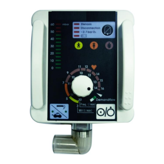
Page 8: The Basics
H-1.601.00024-A3.0 1. The Basics A: AII6000A control panel 1 Mask/tube ventilation switch with indicator LEDs. 2 Ventilation pressure gauge. 3 Alarm panel. 4 Alarm mute button. 5 Respiratory stalls Symbol Meaning Emergency ventilation mode — Toddler Emergency ventilation mode — Child Emergency ventilation mode —... - Page 9 H-1.601.00024-A3.0 2–46...
-
Page 10: Description
H-1.601.00024-A3.0 2. Description 2.1 Uses AII6000A is an automatic oxygen respiration device (short-term ventilator) with additional inhalation facility. You can use AII6000A: To revive patients at the site of the emergency; For longer periods in more protracted emergencies, e.g. fires; ... -
Page 11: Demand Flow Function
H-1.601.00024-A3.0 2.3 Demand flow function The Demand flow setting switches the AII6000A breathing-controlled O2 inhalation. Such inhalation must be carried out with the respiration mask. A small inspiration (trigger) pulse causes oxygen to continue flowing until slight overpressure interrupts the flow. Expiration then takes place via the patient valve as in ventilation. 2.4 Patient valve Φ30mm Convex cone Interface Outlet... -
Page 12: Audio Response
H-1.601.00024-A3.0 2.5 Audio response The device has an audio response facility that can be switched on for user guidance, especially for users who have little practice. If audio response is not required, a key combination can be used to switch it off (See “5.8 Audio responses for user guidance”). -
Page 13: Safety Instructions
H-1.601.00024-A3.0 3. Safety instructions 3.1 Safety regulations For your own safety and that of your patients, please observe the following points: General Please read the directions for use carefully. They are an integral part of the ventilator and must be kept available for reference at all times. ... - Page 14 H-1.601.00024-A3.0 Can cause explosive reactions when high-pressure oxygen and combustible material( grease, oil,alcohol, etc.) meet. This equipment is only suitable for patients weight more than 10KG. NOTE: Please note that a safe distance must be maintained between AII6000A and equipment that emits HF radiation (e.g.
- Page 15 H-1.601.00024-A3.0 Ventilation/Operation Caution: Both patient and ventilator must be kept under constant observation during ventilation. Make sure that neither the outlet nor the emergency air intake on the patient valve are blocked or their function impeded in any other way, e.g. by the patient’s position.
- Page 16 H-1.601.00024-A3.0 the indicating on the knob is aligned with the lower left edge of yellow colorized scale. If not, the device may exist problem, please stop using and contact the manufacturer or the Ambulanc authorized personnel. 9–46...
-
Page 17: Installation
H-1.601.00024-A3.0 4. Installation A permanent mounting is usually necessary only when AII6000A is installed as a fixture in rescue vehicles, helicopters or aircraft .If AII6000A is supplied complete on a carrying platform or in an emergency rucksack, it is ready for use and requires no further installation. -
Page 18: Ventilation Hose
H-1.601.00024-A3.0 3. If the pressure hose is not already connected to the exit from the pressure reducer, make this connection with the 9/16’’-18UNF connecting nut. 4. Screw the other end of the pressure hose on to pressurized gas connection 10 on the AII6000A if this has not yet been done. 4.2 Ventilation hose 1. -
Page 19: Wall Mounting Set
H-1.601.00024-A3.0 3. Connect the patient valve to the other end of the ventilation hose and pressure gauge hose. 4. If a mask is being used for ventilation, attach the mask connection to the patient valve (identical with hose connection), or if the patient is intubated, attach the patient valve to the hose. -
Page 20: Please Check As Below Advised Carefully Before Using
H-1.601.00024-A3.0 4.4 Please check as below advised carefully before using Check power alarm status. Check Respiratory Valve for patients. Check trigger pressure. Check the stenosis alarm.(see “7.4 Checking the alarm systems”) Check the disconnection alarm. (see “7.4 Checking the alarm systems”) ... -
Page 21: Using The Ventilator
H-1.601.00024-A3.0 5. Using the ventilator 5.1 Switching on / self test 1. Open the valve of the oxygen cylinder slowly. The pressure gauge will now show the pressure in the cylinder. 2. Where appropriate, calculate how long the remaining oxygen will last (see “5.9 Calculation of oxygen content/remaining operating time”). -
Page 22: Performing Ventilation
H-1.601.00024-A3.0 Recommended ventilation settings: Yellow Orange Brown Body Weight 10Kg 30Kg 60Kg 80Kg Above 110Kg Respiratory 30bpm 16bpm 11bpm 10bpm 10bpm 13bpm 14bpm frequency Minute volume 3L/min 5L/min 7L/min 9L/min 11L/min 15L/min 16L/min The figures shown in the table are only recommendations. Different settings may be required in cases of pulmonary damage or for special indications. -
Page 23: Monitoring Ventilation
H-1.601.00024-A3.0 patient valve. NOTE: Use this model when patient can not spontaneous breath, this model is invasive breathing. 5.4 Monitoring ventilation Example of ventilation sequence before and after lung compliance diminishes The patient must be monitored constantly during ventilation. You can check the course of ventilation at ventilation pressure gauge 2. High airway resistance, e.g. -
Page 24: Terminating Ventilation Or Demand Flow
H-1.601.00024-A3.0 At higher breath rates, fresh air is automatically mixed in with the oxygen. This is done via the emergency air intake of the patient valve. The Demand Flow mode is ended by turning the regulator knob back to ventilation mode from the index position marked by the white triangle, or by switching off the ventilator. - Page 25 H-1.601.00024-A3.0 < 2,7 bar: Drop in oxygen pressure to below 2.7 bar : Battery charge inadequate All the visual alarms are accompanied by an acoustic alarm. If the ventilator detects a malfunction during the self test after switching on or during continuous operation, the LED light of ventilation pressure gauge on the top left of panel will keep flashing for 5 seconds on 50, 55, and 60 positions, and then enter into working mode.
- Page 26 H-1.601.00024-A3.0 Disconnection alarm As a rule this alarm is due to interruption of the breathing system. The alarm is set off when the rise in pressure fails to reach at least 3 mbar in two successive inspiration phases. If audio response is enabled, the unit announces “Check ventilation system and settings”.
-
Page 27: Audio Response For User Guidance
H-1.601.00024-A3.0 after a short interval. Audio response will also resume automatically. Both the visual and acoustic alarms are cancelled automatically as soon as the malfunction is eliminated. 5.8 Audio response for user guidance Selecting language / Switching off audio guidance The language setting can only be selected if the unit is switched off. - Page 28 H-1.601.00024-A3.0 Audio response messages The following is a list of the individual audio response messages with notes on what they mean: Table 1: Audio response Meaning “Turn on oxygen cylinder” Open oxygen cylinder valve slowly. “Check respiration and select mode” Depending on whether or not the patient is breathing,set AII6000A to one of the modes Demand Flow, mask ventilation...
-
Page 29: Calculation Of Oxygen Content/Remaining Operating Time
H-1.601.00024-A3.0 or adjust the minute volume to suit the patient. “Selected language:Chinese”(English) When selecting the language for the audio response, press the mask/tube switch 1 as many times as necessary until the desired language is announced. “Audio response is off” Confirmation that audio response is deactivated. -
Page 30: Alternative Ventilation Procedures
H-1.601.00024-A3.0 Breathing volume(AZV)= inhalation flow × inhalation time For the above example: Breathing volume=45L/min×0.033min=1.5L Minute volume(MV)=respiratory frequency × AZV For the above example: Minute volume(MV)=10min-1×1.5L=15L/min Real Demand Flow time(min)=Oxygen content(L)/MV(L/min) Example: O2 content= 2000L, MV=15L/min. This gives the following equation: Real Demand Flow time= 2000L/15L/min=133 min= 2h 13min 5.10 Alternative ventilation procedures If AII6000A ceases to function during a ventilation procedure, the following... -
Page 31: Hygienic Preparation
H-1.601.00024-A3.0 6. Hygienic preparation After every use the AII6000A and any accessories used must undergo hygienic preparation. Be sure to carry out a functional check after every hygienic preparation (see “7. Functional checks”). 6.1 AII6000A You can keep AII6000A clean by simply wiping with disinfectant as described in section 6.6. -
Page 32: Masks
H-1.601.00024-A3.0 6.4 Masks Perform the hygienic preparation of the masks as described in section 6.6. 6.5 Fittings For external cleaning of fittings (e.g. pressure reducer, valve), use only a clean cloth. The cloth may be dry or moistened with clean water. Never immerse the fittings in disinfectants or other liquids. - Page 33 H-1.601.00024-A3.0 the opposite direction! 4. Detach the syringe from the pressure gauge hose and empty it out completely. Repeat the procedure 5 more times. 5. After disinfection, the pressure gauge hose must be rinsed with distilled water at least 8 times using the same principle. 6.
-
Page 34: Functional Checks
H-1.601.00024-A3.0 7. Functional checks Before each use, after each dismantling and reassembly, and at the very least every 6 months, the user must carry out functional checks on the ventilator. NOTE: Before carrying out the functional check on AII6000A, you must connect the ventilation hose and the patient valve. -
Page 35: Checking For Leaks In The System
H-1.601.00024-A3.0 7.2 Checking for leaks in the system 1. Open the valve of the oxygen cylinder slowly. You can now read the pressure in the cylinder from the gauge on the pressure reducer. For example, a reading of 200 bars means that the cylinder is full, whereas 100 bars mean it is half full. -
Page 36: Checking The Alarm Systems
H-1.601.00024-A3.0 Caution! When reassembling, make sure that the one-way valve membrane is correctly positioned. 7.4 Checking the alarm systems Warning: In the case of the stenosis alarm and the disconnection alarm, the alarm signal (or message) is only set off when the cause of the alarm is repeated in two successive inspiration phases. - Page 37 H-1.601.00024-A3.0 system has fallen below 2.7 bar, the <2.7 bar O2 alarm should be set off. If audio response is enabled, the ventilator announces “Check pressure hose system and gas supply”. Power supply ( The alarm that indicates a failing battery is checked automatically in the self test that runs when AII6000A is switched on.
-
Page 38: Troubleshooting
H-1.601.00024-A3.0 8. Troubleshooting Fault Cause Remedy AII6000A defective. Arrange for repair. Replace battery in battery compartment. AII6000A will not If ventilator still refuses to switch switch on. Battery failing. on, have internal auxiliary battery replaced by manufacturer or authorized specialists. Airways obstructed. - Page 39 H-1.601.00024-A3.0 Fault Cause Remedy Replace battery battery compartment. If ventilator still refuses to switch Battery failing or fuse Alarm. on, have internal auxiliary defective. battery replaced by manufacturer or authorized specialists. Visual alarms flashing, but no acoustic alarm and Short-term electronic no audio response.
-
Page 40: Servicing
H-1.601.00024-A3.0 9. Servicing 9.1 Intervals NOTE: Always remember to carry out a technical safety check on the ventilator after every repair. AII6000A must undergo a technical safety check and servicing at regular intervals. After each using: Cleaning and disinfecting reusable ventilation hose and patient valve according to the instruction in Chapter VI. -
Page 41: Battery
H-1.601.00024-A3.0 9.3 Battery AII6000A is equipped with one battery: Battery (Li-ion battery 3.7 V) for power supply. It can be changed by the operator. In room temperature environment the full power battery's working time is up to 10 hours. We recommend having the batteries changed only by the manufacturer –Ambulanc–... -
Page 42: Change Valve Membrane In Patient Valve
H-1.601.00024-A3.0 9.4 Change valve membrane in patient valve If one of the valve membranes in the outlet or the emergency air intake interface of the patient valve is crinkled, sticky or misshapen, it must be changed. Emergency air intake 1. Take the emergency air intake interface out of the patient valve. To do so, push the two locking lugs out of their seat, using a small screwdriver, for example. -
Page 43: Product And Accessories
H-1.601.00024-A3.0 10. Product and accessories 10.1 Standard product Accessories Part No. QTY(PCS) AII6000A main unit 2.601.00014 Reusable ventilation hose 1.703.00021 Patient valve 2.602.00019 Reusable mask(Adult) 5.000.00170 AII6000A User manual 1.601.00024 10.2 Optional Accessories Accessories Part No. QTY(PCS) 5.000.00169 Pressure reducer 1.703.00003 Respirator air supply connection pipe 5.000.00174... -
Page 44: Technical Data
H-1.601.00024-A3.0 11. Technical data 11.1 Specifications Device category Internal power supply Dimensions L×H×B in mm 168×110×90 include connectors Weight Approx. 0.6kg Operation: Temperature range, Humidity, 0℃ to +40℃ max. 95% Air pressure 70Kpa to 110 Kpa Control Timing pulse, volume constant Gas input Medical oxygen Operating pressure... -
Page 45: Product Structure Diagram
H-1.601.00024-A3.0 lithium battery 3.7 V; 3 Ah, -10℃ ~ Power supply Life expectancy +60℃ Max. charge cycles Charge-discharge cycle 500 times Reusable ventilation hose Spiral silicone Degree of protection against water IPX4 Standards complied with IEC60601-1 IEC60601-1-2 EN794-3 EN1789 Pressure gauge accuracy Deviation -1~+4.99mbar Trigger sensitivity Deviation ±... -
Page 46: Relationship Between Ventilation Parameters
H-1.601.00024-A3.0 11.3 Relationship between ventilation parameters The following diagram shows the relationship between the ventilation parameters “minute volume” and “respiratory frequency”: 39–46... -
Page 47: Warranty
H-1.601.00024-A3.0 12. Warranty Ambulanc provides one year warranty from the date of purchasing and lifelong maintenance. Suggested Product’s life:Three years. Claims against the warranty can be made only when accompanied by the sales receipt, which must show salesperson and date of purchase. ... -
Page 48: Storage And Transportation
H-1.601.00024-A3.0 13. Storage and transportation Packaged product can be transported by truck, air or railway. During the transportation, should avoid shock, severe vibration and moisture. Transport temperature is -40 ℃ ~ +50 ℃, relative humidity should be less than 95%. Storage temperature -40 - 50℃... -
Page 49: Emc Declaration
H-1.601.00024-A3.0 14.EMC declaration 14.1 Guidance and manufacturer’s declaration – electromagnetic emission – for all EQUIPMENT and SYSTEMS Guidance and manufacturer´ s declaration – electromagnetic emission The AⅡ6000A emergency ventilator is intended for use in the electromagnetic environment specified below. The customer or the user of AⅡ6000A emergency ventilator should assure that it is used in such an environment. -
Page 50: Equipment And Systems
H-1.601.00024-A3.0 – 14.2Guidance manufacturer's declaration electromagnetic immunity – for all EQUIPMENT and SYSTEMS Guidance and manufacturer’s declaration – electromagnetic immunity The AⅡ6000A emergency ventilator is intended for use in the electromagnetic environment specified below. The customer or the user of the AⅡ6000A emergency ventilator should assure that it is used in such an environment. -
Page 51: Guidance And Manufacturer's Declaration - Electromagnetic Immunity
H-1.601.00024-A3.0 Power Power frequency magnetic fields frequency should be at levels characteristic (50/60 Hz) 3 A/m 3 A/m of a typical location in a typical magnetic field commercial or hospital IEC61000-4-8 environment. NOTE: U is the a. c. mains voltage prior to application of the test level. 14.3 Guidance and manufacturer’s declaration –... - Page 52 H-1.601.00024-A3.0 according to the transmitter manufacturer and d is the recommended separation distance in meters (m). Field strengths from fixed RF transmitters, as determined by an electromagnetic site survey, should be less than the compliance level in each frequency range. Interference may occur in the vicinity of equipment marked with the following symbol:...
-
Page 53: Recommended Separation Distances Between Portable And Mobile Rf Communications Equipment And The Equipment Or System
H-1.601.00024-A3.0 14.4 Recommended separation distances between portable and mobile RF communications equipment and the EQUIPMENT or SYSTEM Recommended separation distances between portable and mobile RF communications equipment and the AⅡ6000A emergency ventilator The AⅡ6000A emergency ventilator is intended for use in an electromagnetic environment in which radiated RF disturbances are controlled.
Need help?
Do you have a question about the D-Tiger AII6000A and is the answer not in the manual?
Questions and answers