
Related Manuals for MasterForce STB456


Summary of Contents for MasterForce STB456
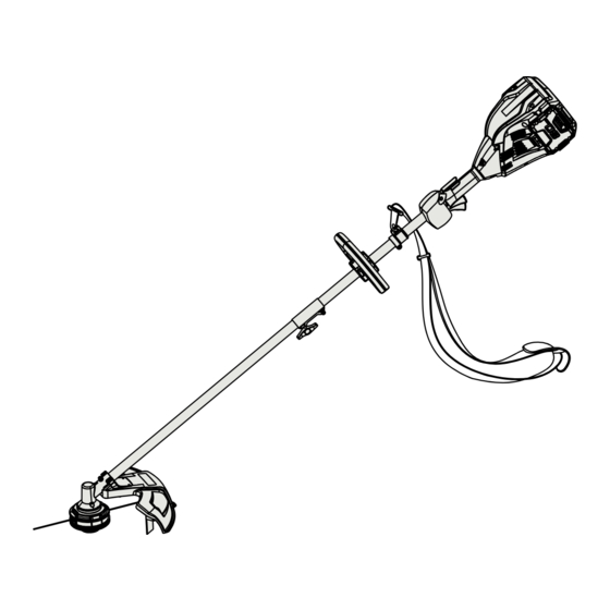
- Page 1 80V BRUSHLESS STRING TRIMMER 267-3199 2100194ME STB456 OPERATOR’S MANUAL CAUTION To Reduce The Risk Of Injury, User Must Read And Understand Operator’s Manual. Save These Instructions For Future Reference.
-
Page 2: Table Of Contents
TABLE OF CONTENTS Safety Symbols ......................Page 2 Safety Instructions ...................... Page 3 Overview ........................Page 7 Assembly ........................Page 8 Operation ........................Page 11 Maintenance ......................Page 14 Troubleshooting ......................Page 15 Notes ........................Page 17 Warranty ........................Page 18... -
Page 3: Safety Symbols
SAFETY SYMBOLS Some of the following symbols may be used on this product. Please study them and learn their meaning. Proper interpretation of these symbols will allow you to operate the product better and safer. Symbol Name Designation / Explanation Volts Voltage Amperes... -
Page 4: Safety Instructions
SAFETY INSTRUCTIONS The purpose of safety symbols is to attract our attention to possible dangers. The safety symbols, and the explanations with them, deserve your careful attention and understanding. The symbol warnings do not by themselves eliminate any danger. The instructions and warnings they give are no substitutes for propper accident prevention measures. - Page 5 • Don’t use in the rain. Store indoors. • Use only Masterforce Batteries: BAB726 or • Do not operate in poor lighting. other BAB series. • Keep all parts of your body away from any •...
- Page 6 SAFETY INSTRUCTIONS parts and accessories. Use of any other then neutralize with lemon juice or vinegar. parts may create a hazard or cause product If liquid gets into your eyes, flush them with damage. clean water for at least 10 minutes, then seek •...
- Page 7 SAFETY INSTRUCTIONS instructions for use and care. PROPOSITION 65 This product contains a chemical known to the state of California to cause cancer, birth defects or other reproductive harm. Some dust created by power sanding, sawing, grinding, drilling, and other construction activities contains chemicals known to cause cancer, birth defects or other reproductive harm.
-
Page 8: Overview
OVERVIEW SPECIFICATIONS Type Cordless, battery operated Motor 80V Brushless String Cutting Width 14/16 in. String Diameter 0.08" (2.0 mm) Speed 5000/5500 RPM Weight (Without Battery) 10.6 lbs (4.8 kg) The recommended ambient temperature range: Item Temperature String trimmer storage emperature range -4°F (-20°C) - 158°F (70°C) String trimmer operation temperature range -4°F (-20°C) - 104°F (40°C) -
Page 9: Assembly
ASSEMBLY UNPACKING ATTACHMENT This product requires assembly. Read and understand entire Operator’s Manual for each optional attachment used on • Carefully remove the product and any this power head and follow all warnings and accessories from the box. Make sure that instructions. - Page 10 ASSEMBLY The attachment connects to the power head LINE TRIMMER CUT-OFF BLADE by means of a coupler device. 1. Loosen the attachment knob on the The trimmer is equipped with a line trimming coupler. cut-off blade on the guard. Replace the string 2.
- Page 11 ASSEMBLY THE BATTERY PACK The trimmer is currently set at a 14 in. cutting swath. To adjust to a cutting swath of 16 in.: • If the battery pack WARNING 1. Remove the battery from the string or charger is dam- trimmer.
-
Page 12: Operation
OPERATION OPERATION TIPS WARNING Read and under- • Hold the power head with your right hand stand entire Operator's Manual for each on the rear handle and your left hand on optional attachment used on this power the auxiliary handle. Keep a firm grip with head and follow all warnings and instructions. - Page 13 OPERATION INSTALL STRING IN THE STRING REMOVE THE OLD TRIMMER HEAD LINE 1. Firmly press in the tabs on each side of the spool cover. 2. Remove the spool cover from the spool housing. 3. Remove any excess trimmer line or obstructions from the spool.
- Page 14 OPERATION REMOVE THE OLD TRIMMER CUTTING TIPS LINE • Keep the trimmer tilted toward the area 1. Line up the spacer hole up with the hole in being cut; this is the best cutting area. the gear box. • The trimmer cuts when passing the unit 2.
-
Page 15: Maintenance
MAINTENANCE STORING THE POWER HEAD WARNING When servicing, • Clean all foreign material from the product. use only identical replacement parts. Use • Store it in a well-ventilated place that is of any other parts may create a hazard or inaccessible to children. -
Page 16: Troubleshooting
TROUBLESHOOTING PROBLEM POSSIBLE CAUSE SOLUTION The machine does No electrical contact 1. Remove battery pack. not start between the machine 2. Check contact and install the battery pack when you push the and the battery pack. again. trigger. The battery pack is Charge the battery pack. - Page 17 TROUBLESHOOTING The line keeps The machine is used 1. Cut with the tip of the line, avoid stones, breaking. incorrectly. walls and other hard objects. 2. Advance the cutting line regularly to keep full cutting width. The grass winds Cut tall grass at 1.
-
Page 18: Notes
EXPLODED VIEW ITEM NO. PART NO. DESCRIPTION RB34130334V Auxiliary assembly RB37902144 Shoulder strap R0201682-00 Coupler bolt R0201683-00 Coupler knob R0201684-00 Guard assembly R0201685-00 Trimmer head assembly Page 17... -
Page 19: Warranty
WARRANTY 4-YEAR LIMITED WARRANTY This MASTERFORCE™ brand power tool carries our famous No Hassle 4-Year Limited Warranty to the original purchaser. If, during normal use, this MASTERFORCE™ power tool breaks or fails due to a defect in material or workmanship within four (4) years from the date of original purchase, simply bring the tool with the original sales receipt back to your nearest MENARDS ®... - Page 20 © 2019 Menard, Inc., Eau Claire, WI 54703 12/2019 Page 19...
Need help?
Do you have a question about the STB456 and is the answer not in the manual?
Questions and answers
Install string on masterforce weedeater
To install string on the MasterForce weedeater STB456:
1. Line up the slots on the spool cap with the slots on the string head.
2. Insert the trimmer line through the hole in the string head and push it until it exits the opposite hole.
3. Pull the line until equal lengths are on both sides.
4. Turn the spool cap clockwise to wind the line into the string head.
5. Leave about 5 inches of line protruding from each side.
Recommended line diameter is 0.080 inches.
This answer is automatically generated