DPE Medical DST8000 Triple Unpacking And Assembly Instructions
Hide thumbs
Also See for DST8000 Triple:
- User manual (12 pages) ,
- Unpacking and assembly instructions (19 pages) ,
- Unpacking and assembly instructions (14 pages)
Advertisement
Quick Links
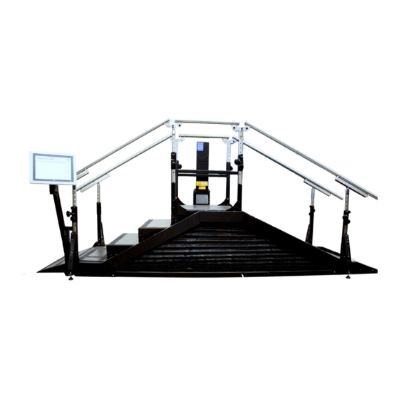
DST8000 Triple and DST8000 Triple Pro
Unpacking and Assembly Instructions
General Instructions:
1. Colors, details, and accessories may differ as per your model.
2. Relevant fasteners for each step are attached in small plastic bags near their place of assembly.
3. All needed tools are attached.
4. Keep packing materials, tools, and instructions if repackaging of the DST is an option.
5. Tighten firmly all bolts and nuts as shown.
6. Most assembly instructions must be performed on both sides of the device (drawings shows one
side).
7. The DST8000 Triple requires one grounded socket. the DST8000 Triple Pro requires two
grounded sockets.
8. After assembly, read the User Guide.
9. If assistance is needed, contact your distributor. You can also contact the manufacturer at:
info@dpemed.com
Important
A. It is essential to carefully read these instructions before assembling the device.
B. If you have any questions or if you are uncertain how to proceed, stop and contact
support at: info@dpemed.com
C. Pictures may vary, depending on your model.
Two people are needed to assemble the device.
D.
E. To activate your warranty fill the online warranty form at:
www.dpemed.com/dst-registration
1
(ver-18)
Advertisement

Related Manuals for DPE Medical DST8000 Triple

Summary of Contents for DPE Medical DST8000 Triple
- Page 1 6. Most assembly instructions must be performed on both sides of the device (drawings shows one side). 7. The DST8000 Triple requires one grounded socket. the DST8000 Triple Pro requires two grounded sockets. 8. After assembly, read the User Guide.
- Page 2 Where to locate your DST? a. Make sure that the ceiling height is at least 2.6 meter. b. Both sides of the DST must be spacious enough to allow the physiotherapists to move freely around the device to adjust the handrails. A clearance of 50 cm is recommended at both sides of the DST. c.
- Page 3 Index of parts: Part #1 - right small slope cover x1 Part #2 - left small slope cover x1 Part #3 - diagonal reinforcement x4 Part #4 - internal post x2 Part #5 - left long slope cover x1 Part #6 - right long slope cover x1 Part #7 - Stair rail x2 Part #8 –...
- Page 4 1. Each package has a drawing attached to it. Remove the part from the package only when needed for assembly. Example for parts’ packaging For Computerized version only: during the assembly you will connect two low current electrical sockets/outlets, like this: 3.
- Page 5 7. Remove the remaining walls of the crate. 8. Take out all wrapped parts. Leave them in their packages until they will be assembled. 9. Part #9 (main part of the DST Triple, which is now on the crate's floor), has retractable wheels.
- Page 6 11. Important: retrack the wheels when the main part is in its final location. As in instruction #9 – use the lifting handle to turn back the front and rear lever 12. Instructions on where and how to locate the device in the room: Electric cable/cables (16 in.) (48 in.)
- Page 7 14. After placing part #9 at its final location and retracking its wheels, connect part #10 as shown. Part #10 Part #9 Remove the nut and spring washer on both sides. Place part #10 as shown. Make sure both sides of the part are located the same.
- Page 8 Section 15 is applicable only for DST8000 Triple Pro – computerized model 15. Connect the tied plug to the socket as shown. Before After connecting Note: Don't place wires above this bracket Take out the attached zip ties and use them to hold the connected plug to the socket.
- Page 9 16. unfold the main slope. This part consists of two slopes – a big ramp and a small one connected to it. a. Make sure to hold both ramps when unfolding the part. b. Two people are needed for this action. c.
- Page 10 small ramp big ramp...
- Page 11 Section 17 is applicable only for DST8000 Triple Pro – computerized model 17. Connect the plug to the socket as shown. Lie down and look at the direction of arrow. will connectors marked below as A and B. Connect them together.
- Page 12 18. Unfold the little ramp. 19. Remote the white zip ties and press the black fasteners of the bellow into the holes located on the frame of the slope. Remove the white zip ties. Insert the bellow’s black press-fasteners to the appropriate holes in the frame.
- Page 13 20. Connect the bellow track to the big ramp by placing and tightening the bolts with the spring washers. Repeat this action on both sides of the ramp. The necessary bolts and washers are attached to each track. Overview when the bellow is assembled:...
- Page 14 21. Assemble part #1 (right small slope cover) as shown. Repeat this action on the other side of the ramp with part #2. A - Insert part #1 to the external post as shown. and lower it as shown. Turn part #1 clockwise C - Insert bolts with the spring washers and tighten.
- Page 15 22. Assemble part #6 (right long slope cover) as shown. Place the part as shown. Place and tighten all 5 bolts with the washers. Make sure the part is located appropriate, as shown. Repeat the same action on the other side with part #5.
- Page 16 23. Assemble part #3 (diagonal reinforcement) as shown. A – Place part #3 as shown. B – place and tighten the 4 bolts and nuts as shown. Assemble the remaining 3 diagonal reinforcements in the same way.
- Page 17 Section 25 is applicable only for the DST8000 Triple Pro 24. Computer setup. A Cut the plastic zip-tie and raise the computer. Cut the Zip-tie B Remove the bolt and keep it...
- Page 18 Section 25 is applicable only for the DST8000 Triple Pro C rotate the compute’s arm outwards. D Place and tighten the bolt you removed in part B...
- Page 19 25. Unfold the stairs’ access slope.
- Page 20 26. Assemble part #7 (stair rail-right).
- Page 22 27. Insert part #4 as shown. Unlock tightening knob, pull the spring plunger and insetr the pole. Spring plunger Tightening knob 28. Repeat this action for all other handrails (part #7 x1, part #8 X2) Part #8 – Slope’s handrails Part #7 –...
- Page 23 DST8000 Triple models Maintenance A yearly inspection is recommended. Configuration and colors may differ, depending on your model. 1. Visual inspection a. Make sure that the ceiling height is at least 2.6 meter. b. Make sure that no objects or other equipment is touching the DST or too close to it.
Need help?
Do you have a question about the DST8000 Triple and is the answer not in the manual?
Questions and answers