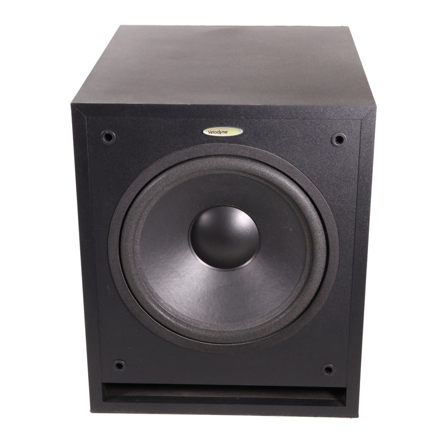
Velodyne CHT-8, CHT-10, CHT-12 - Subwoofer System Manual
- Owner's manual (12 pages) ,
- Owner's manual (6 pages) ,
- User manual (25 pages)
Advertisement
SAFETY INSTRUCTIONS

RISK OF ELECTRIC SHOCK
DO NOT OPEN

To reduce the risk of electric shock, do not remove cover (or back). No user-serviceable parts inside. Refer servicing to qualified service personnel.
The lighting flash with arrowhead symbol is intended to alert the user to the presence of uninsulated "dangerous voltage" within the product's enclosure that may be of sufficient magnitude to constitute a risk of electric shock to persons.
The exclamation point symbol is intended to alert the user to the presence of important operating and maintenance (servicing) instructions in the literature accompanying the subwoofer.
- Read Instructions -- All safety and operating instructions should be read before the subwoofer is operated.
- Retain Instructions -- The safety and operating instructions should be retained for future reference.
- Heed Warnings -- All warnings on the subwoofer and in the operating instructions should be adhered to.
- Follow Instructions -- All operating and use instructions should be followed.
- Water and Moisture -- The subwoofer should not be used near water -- for example, near a bathtub, washbowl, kitchen sink, laundry tub, in a wet basement, near a swimming pool or the like.
- Carts and Stands -- The subwoofer should be used only with a cart or stand recommended by the manufacturer.
- Wall or Ceiling Mounting -- The subwoofer should be mounted to a wall or ceiling only as recommended by the manufacturer.
- Ventilation -- The subwoofer should be situated so that its location or position does not interfere with its proper ventilation. For example, the subwoofer should not be situated on a bed, sofa, rug, or similar surface that may block the ventilation openings; or placed in a built-in installation such as a bookcase or cabinet that may impede the flow of air through the ventilation openings.
- Heat -- The subwoofer should be situated away from heat sources such as radiators, heat registers, stoves, or other subwoofers that produce heat.
- Power Sources -- The subwoofer should be connected to a power supply only of the type described in the operating instructions or as marked on the subwoofer.
- Power-Cord Protection -- Power-supply cords should be routed so that they are not likely to be walked on or pinched by items placed upon or against them, paying particular attention to cords at plugs, convenience receptacles, and the point at which they exit from the subwoofer.
![]()
To prevent electrical shock, match wide blade of plug to wide slot, fully inserted.- Cleaning -- The subwoofer should be cleaned only as recommended by the manufacturer.
- Non use Periods -- The power cord of the subwoofer should be unplugged from the outlet when left unused for a long period of time.
- Object and Liquid Entry -- Care should be taken so that objects do not fall and liquids are not spilled onto the enclosure.
- Damage Requiring Service -- The subwoofer should be serviced by qualified service personnel when:
- The power-supply cord or plug has been damaged.
- Objects have fallen or liquid has been spilled into the subwoofer.
- The subwoofer has been exposed to rain.
- The subwoofer does not appear to operate normally or exhibits a marked change in performance.
- The subwoofer has been dropped or damaged.
- Servicing -- The user should not attempt to service the subwoofer beyond what is described in the operating instructions.
All other servicing should be referred to qualified service personnel.
Congratulations!
Congratulations on your purchase of a Velodyne subwoofer system. This system represents the state of the art in low frequency reproduction. Read and follow the instructions below to insure safe and proper system operation.

To prevent fire or shock hazard, do not expose this equipment to rain or moisture. To avoid electrical shock, do not open speaker enclosure or amp chassis cover. Please observe all warnings on the equipment itself. There are no user serviceable parts inside. Please refer all service questions to your authorized Velodyne dealer.
Prior to installation
Please unpack the system carefully. Remove all staples used to seal the carton as they can scratch the cabinet. Please save the carton and all packaging materials for future use. Record the serial number in the space provided on the warranty card for future reference.
Product Features and Controls
- Built-in 130 watt (RMS) power amplifier (CHT-8)
- Built-in 150 watt (RMS) power amplifier (CHT-10)
- Built-in 170 watt (RMS) power amplifier (CHT-12)
- Subwoofer Direct - switchable crossover bypass
- Adjustable (40 to 120Hz) low-pass crossover
- Selectable (80 or 100Hz) high-pass crossover (CHT-12)
- 85 Hz high-pass crossover (CHT-80/CHT-10)
- Line-level inputs and outputs
- Speaker-level inputs and outputs
- Signal sensing auto turn on/off with bypass option
- Variable volume control
- Selectable phase control (0 or 180 degrees)
- Dual staggered low-pass crossover; 12dB/octave initial, 24dB/octave ultimate
- Anti-clipping circuit
- Over excursion protection
Installation
Your new subwoofer system provides for a number of installation options. Read all the installation information below in order to determine which installation option is best for your system. Remember to perform all installation procedures with system power turned off.
Inputs
Your new subwoofer is equipped with both speaker-level and line-level inputs. Use the RCA/Phono type "INPUT" jacks when connecting your subwoofer to a pre-amp, signal processor, or line-level crossover. The "SPEAKER LEVEL-INPUT" jacks connect directly to the speaker outputs of a integrated amplifier or receiver. Your amplifier section will notice no additional loading effects when you use these inputs because of their high impedance.
 Note:
Note:
Do not use both the RCA/Phono "INPUT" connections and "SPEAKER LEVEL-INPUT" connections simultaneously.
Volume control
This control allows you to balance the output from the subwoofer to the main speakers in your system. This control should be set to achieve similar volume level from both the main speakers and subwoofer.
Low-pass crossover
Both sets of inputs sum the left and right channels together and the resulting signal is passed through an adjustable low-pass crossover before being amplified. The crossover control allows you to adjust the upper limit of the subwoofer's frequency response from 40 to 120 Hz. The subwoofer's response will begin rolling off above the frequency you set this control to.
You should set the crossover frequency to obtain a smooth and seamless transition from the subwoofer to the main speakers in your system. If your main speakers are smaller units with limited low frequency output, you may wish to choose a higher frequency (such as 100-120Hz) than you would with larger speakers which have greater low frequency output. With larger speakers, you might start with this control set lower, such as 80Hz.
Subwoofer Direct
A bypass switch is also provided if you wish to use an external crossover. If you are not using an external crossover, we recommend that you use the one provided within the unit for optimum performance.
Phase adjustment- 0˚/180˚
This control allows you the "reverse" the phase of the subwoofer's output signal 180˚ to correct for any possible mismatch and resulting cancellation between the subwoofer and your main speakers/amplifier. To adjust, simply listen to the system with music playing. Then move the switch from one position to the other and listen for a change in low frequency output. The correct position will have a greater amount of apparent low frequency output.
Auto turn on function
With this function in the "auto" position, your CHT-8/CHT-10/CHT-12 can be safely left with the main power switch on continuously. The subwoofer will turn itself on automatically when an audio signal is present. If no signal is present for approximately 10 minutes, the unit will switch to standby mode. While in standy mode, your subwoofer will draw very minimal power. This function can be disabled by leaving the switch in the "on" position.
High pass crossover switch (CHT-12)
This switch selects the frequency for the high pass crossover. This crossover is functional on both line and speaker-level outputs. Smaller speakers with limited low frequency output may prefer the higher 100Hz setting which will reduce the low frequencies sent to them. Larger speakers with greater low frequency output may be able to handle the 80Hz setting without strain.
Power switch
The master power switch is located on the right half of the unit. This rocker style switch is the main on/off for the unit. This switch should be set to position 1 for on (up), 0 for off (down).
Line-level connection
Figure 1 shows connection to a pre-amplifier's main outputs and returning them to your amplifier inputs.

Figure 1: Installation using line-level (RCA/Phono jack) inputs
When installed in this fashion, your satellite speakers will be crossed over at 80/100Hz (or 85Hz for CHT-8/-10) which removes the lower bass from your amplifier and speakers, enabling them to do a better job reproducing high frequencies. By utilizing this method, you will have a bi-amplified system, gaining improved power and headroom for your system.
Subwoofer outputs
The Velodyne subwoofer is designed to operate using the full range audio signal for input when using the built-in crossover. Many home theater processors/receivers (Dolby Digital, DTS, THX) have a "subwoofer out" jack that is internally filtered and designed to be used with a powered subwoofer.
In these installations, you may bypass the internal crossover in either the processor or the Velodyne subwoofer. In some installations, it may be beneficial to have a steeper ultimate crossover slope. To do this you can use both your processor's crossover and the one internal to the Velodyne sub. You should stagger the frequencies (i.e., 120Hz sub, 80Hz processor) for best results.
To bypass the subwoofer's internal crossover when the unit is being fed a low pass signal from another crossover, simply locate the switch marked "SUBWOOFER DIRECT/INTERNAL X-OVER" on the rear panel of the subwoofer and set to the "SUBWOOFER DIRECT" position. This will eliminate the internal crossover from the signal path.
Note. . .
If not using an external crossover, you should use the built-in crossover for optimal performance. When using a single channel input signal (such as a surround sound processor's subwoofer out, or LFE), the auto on/off circuit sensitivity will be affected. When one input channel is used instead of two, the unit will see lower signal levels present at the inputs. This may cause the unit to turn off when listening at low volume levels. If this occurs, simply use a "Y" adapter (available from most dealers) to allow your processor's single sub line to be fed into both L&R inputs. This will make the unit turn on at lower signal levels.
Speaker-level connection
Figure 2 shows an easy way to connect your Velodyne subwoofer directly to your receiver or integrated amplifier.

Figure 2: Installation using SPEAKER LEVEL INPUTS (from amplifier)
When connected in this fashion, your satellite speakers will be crossed over at 80/100Hz (or 85Hz for CHT-8/-10), which removes the lower bass from your speakers, enabling them to do a better job reproducing high frequencies.
You may also connect your satellites directly to your receiver or amplifier along with the subwoofer if you wish to bypass the internal high-pass crossover.
To avoid damage to your main amplifier, be sure to maintain correct polarity when making all connections. Red (positive) to red, and black (negative) to black. Be sure that all connections are tight, and that there are no loose strands or frayed wires.
Interconnect cables
When installing your new Velodyne subwoofer using the line-level connections, you should always use shielded phono cables. There are many decent cables available today, most any of which will work perfectly well. We do recommend that you keep the length of cable as short as possible to avoid any potential noise problems.
When using speaker level connections, use a decent quality speaker cable that mates well with the connectors. Be very careful to avoid any loose strands or frayed wires which may result in a short, which may damage your equipment. Cables of extremely large size are typically not required. Extremely large gauge wire may not properly fit in the binding posts, resulting in a poor connection and possible short circuits.
Placement
True subwoofers operate at extremely low frequencies which are primarily omni-directional. While it is recommended that the subwoofers be placed on the same plane as the satellite speakers, room and system conditions often dictate otherwise. Keep in mind that frequency response and output level can be drastically influenced by placement, depending on the acoustic properties of the listening room. Typically, the optimum location for a subwoofer is tucked away in a corner of your listening room. This location will usually offer the greatest output levels and optimum low frequency extension. The worst location for a subwoofer it typically far away from any walls, and close to the center of your room. Avoid these locations when possible. When using a pair of Velodyne subwoofers in stereo, it is preferable to place each subwoofer by the satellite of the same channel. Typically, a minimum distance of 1 to 2 feet from your TV to the subwoofer will be adequate to avoid any magnetic interferance.
This subwoofer has electronics built into the cabinet. Do not place the cabinet next to sources of heat such as furnace registers, radiators, etc. Do not place the unit near sources of excessive moisture, such as evaporative coolers, humidifiers, etc. The power cord should be routed in such a way that it will not be walked on, pinched, or compressed in any way that could result in damaging the insulation or wire.
Care of your subwoofer
Do not use any harsh detergents or chemicals to clean the cabinet. Abrasives, detergents, or cleaning solutions may damage the finish on the cabinet. We recommend using a damp cloth to clean the cabinet.
During normal conditions, the subwoofer may be left on continuously without any problems. The unit is equipped with a signal sensing circuit that will automatically turn on the unit when a signal is present at the inputs and turn off the unit after several minutes when there is no longer any signal at the inputs.
If you plan to leave the unit unused for an extended period of time, we recommend that you turn off the unit by the master power switch on the rear panel.
Troubleshooting and Service
Before seeking service for your subwoofer, please re-check all systems. Following is a simple troubleshooting guide to assist you.
- Verify unit is plugged in and power outlet used is active.
- Is power switch on?
- Is auto turn on/off set properly?
- Is unit receiving an input signal from your source?
- Have all controls on subwoofer (volume, crossover, phase, etc.) been properly set?
- If unit has been running at high levels, one of the protection circuits maybe engaged.
- Has the built-in amplifier overheated?
If the protection circuitry is active, the unit may cycle on and off until operating parameters return to normal. Under more serious conditions, the unit may shut off completely. Normal operation will return upon cooling, but you may be required to turn the power off and then on again to reset the unit.
The following conditions require service by a qualified technician:
- The power cord has become damaged.
- The unit does not appear to operate normally or exhibits a marked change in performance.
- The unit has been exposed to water.
- Some part of the cabinet or circuitry is physically damaged.
SPECIFICATIONS
| CHT-8 | CHT-10 | CHT-12 | |
| Cabinet (H,W,D) | 15" x 12" x 18" | 16.25" x 15" x 21" | 18" x 15" x 21" |
| Frequency Response | 35Hz-140Hz | 28Hz-120Hz | 25Hz-120Hz (±3 dB) |
| High Pass Crossover Passive 85Hz (6 dB/octave slope) | Passive 85Hz | Passive 85Hz | 80Hz or 100Hz |
| Low Pass Crossover | 40Hz -120Hz (12 dB/octave, 24 dB ultimate) | ||
| Amplifier (Class A/B) | 350 watts/ 130 watts RMS power | 375 watts/ 150 watts RMS power | 400 watts/ 170 watts RMS power |
| Woofer | 8" forward firing | 10" forward firing | 12" forward firing |
| Magnet | 40 oz. | 40 oz. | 55 oz. |
| Voice Coil | 2" two-layer copper | 2" four-layer copper | 2" four-layer copper |
| Inputs | Line-level and speaker-level | ||
| Outputs | Line-level and speaker-level | ||
| Warranty | Two years (parts and labor) | ||
| Weight | 44 lbs. (approx.) | 53 lbs. (approx.) | 60 lbs. (approx.) |
Specifications are subject to change without notice.
Velodyne Acoustics, Inc.
345 Digital Drive Morgan Hill, CA 95037
408.465.2800 voice
408.779.9227 fax
408.779.9208 service fax
Web Site: www.velodyne.com
Service E-mail: sevice@velodyne.com
Product E-mail: help@velodyne.co
Technical E-mail: techhelp@velodyne.com

Documents / Resources
References
Download manual
Here you can download full pdf version of manual, it may contain additional safety instructions, warranty information, FCC rules, etc.
Download Velodyne CHT-8, CHT-10, CHT-12 - Subwoofer System Manual
Advertisement


Need help?
Do you have a question about the CHT-8 and is the answer not in the manual?
Questions and answers