Advertisement
Quick Links
Support and E-Warranty Certificate https://www.vevor.com/support
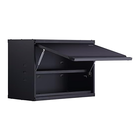
INSTRUCTIONS FOR TOOL CABINET
ASSEMBLY
We continue to be committed to provide you tools with competitive price.
"Save Half", "Half Price" or any other similar expressions used by us only represents an
estimate of savings you might benefit from buying certain tools with us compared to the major
top brands and doses not necessarily mean to cover all categories of tools offered by us. You
are kindly reminded to verify carefully when you are placing an order with us if you are
actually saving half in comparison with the top major brands.
Advertisement

Subscribe to Our Youtube Channel
Related Manuals for VEVOR WC30


Summary of Contents for VEVOR WC30
- Page 1 Support and E-Warranty Certificate https://www.vevor.com/support INSTRUCTIONS FOR TOOL CABINET ASSEMBLY We continue to be committed to provide you tools with competitive price. "Save Half", "Half Price" or any other similar expressions used by us only represents an estimate of savings you might benefit from buying certain tools with us compared to the major top brands and doses not necessarily mean to cover all categories of tools offered by us.
- Page 2 CustomerService@vevor.com This is the original instruction, please read all manual instructions carefully before operating. VEVOR reserves a clear interpretation of our user manual. The appearance of the product shall be subject to the product you received. Please forgive us that we won't inform you again if there are any technology or software updates on our product.
-
Page 3: Assembly Parts List
Please read instructions carefully before assembly. Warning-To reduce the risk of injury, user must read instructions manual carefully. Assembly Parts List Part Description Left side panel Right side panel Back panel Top cover Bottom Shelf Door Wall Hang panel - 2 -... -
Page 4: Part Description
Part Description Hang top panel Hang bottom panel Gas spring Bolt-M3x6 Bolt-M6x15 Screw-ST6.3*38 Rubber plug 8*40mm Positioning board Tools are required for assembly: 1. Phillips screwdriver. 2.Rubber mallet. Safety Tips: 1.Lay a soft cloth or paper on the floor before assembly to prevent the floor from scratching the parts. -
Page 5: Instructions For Installation
Table of Parameters Items Description Name Tool Cabinet Model WC30 770×318×500 mm External dimensions 30.3×12.5×19.7 inch Package Size 850×590×135 mm G.W. 15.5 kg Instructions for Installation STEP 1 Insert back (3)into the buckles of left side plate(1) and right side plate(2). Then use gelatin hammer to flap until the alignment at the top and secure them with bolt- M6*15(13). - Page 6 STEP 2 Step 2: Align bottom’s(5) and hang bottom panel’s(10) holes to left and right side panel’ bottom holes, and secure them with (13)M6x15. (5) Bottom (11) Bolt M6x15 (10)hang bottom panel - 5 -...
- Page 7 STEP 3 Do the same to top cover(4) and hang top panel(9), secure them with bolt-M6x15(13). (13) Bolt M6x15 (4) Top cover (9) Hang top panel - 6 -...
- Page 8 STEP 4 Tilt the shelf (6) into the box, place the shelf from top to bottom, and insert the left, right and back sides of the shelf into the left and right side panels and the backplane hanging brackets at the appropriate height. The installation is complete. (6) Shelf - 7 -...
- Page 9 STEP 5 As shown in the figure, first insert the dowel on the top left of the door into the left side panel hole, and then insert the dowel on the top right of the door into the right panel hole. (7)Door - 8 -...
- Page 10 STEP 6 Before installing the gas spring (11), it is necessary to disassemble the spring support (as shown in the figure), install the base and the pressure rod of the support on the door panel and the box body respectively, lock and fix them with the 11-word large flat head screw M3x6, and then fix the base and pressure rod of the spring support with the removed screws.
- Page 11 STEP 7 As shown in the figure, first paste the positioning board (16) on the wall to draw the positioning line and drill holes, then install the rubber plug (15) into the wall with drilled holes, and then align the mounting hole of the wall hang plate(8) with the installation hole of the rubber plug and use the screw-ST6.3x38(14)to lock and fix .
- Page 12 Support and E-Warranty Certificate https://www.vevor.com/support...
Need help?
Do you have a question about the WC30 and is the answer not in the manual?
Questions and answers