
Related Manuals for APO DK-9827 MK-II


Summary of Contents for APO DK-9827 MK-II
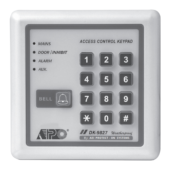
- Page 1 MULTI-PURPOSE DIGITAL ACCESS CONTROL KEYPAD By AEI PROTECT - ON SYSTEMS DK-9827 MK-II Programming & Installation Manual FOR ELECTRIC LOCK, INTER-LOCK AND SECURITY SYSTEM INSTALLATIONS...
-
Page 2: Table Of Contents
TABLE OF CONTENTS INTRODUCTION ······························································································································· 3 ······················································ 3-7 DESCRIPTION OF CONNECTION TERMINALS & INDICATORS ················································································································· 4-6 Connec�on Terminals ························································································································· 6 The LED Indicators ··········································································· 6 The Pacifier Tones & The LED Indica�ng Signals STANDARD PROGRAMMING SUMMARY CHART ·········································································· 7-9 SETTING & PROGRAMMING ······································································································... -
Page 3: Introduction
INTRODUCTION DK-9827 is a self-contained, weatherproof digital access control keypad that offers field proven INTRODUCTION reliability and cost effec�ve solu�ons for residen�al and commercial installa�ons. It is designed for DK-9827 is an universal, self-contained, weatherproof digital access control keypad o ers eld proven reliability and stand alone electric lock and inter-lock systems opera�ng with 12V DC power supply. -
Page 4: Connec�On Terminals
CONNECTION TERMINALS 1 - 2 : TAMPER N.C. ● Normally Closed contact while the keypad is secured on the box. It is open while keypad is separated from the box. Connect this N.C. terminal to a 24 hour zone of an alarm system if necessary. - Page 5 13 : DOOR SENS -- DOOR POSITION SENSOR INPUT ● A Normally Closed (N.C.) input terminal referring to (–) ground. With the help of a normally closed magne�c door switch, the system monitors the posi�on of open or closed of the door and will give the following func�ons: NOTE: Always connect this terminal to (–) ground if not used.
-
Page 6: The Led Indicators
18 - 19 - 20 : OUTPUT 2 ● This is an auxiliary relay output with 1 Amp ra�ng Normally Open (N.0.) and Normally Closed (N.C.) dry contacts controlled by the group 2 user codes, which is ideal for controlling security systems & automa�c operators. -
Page 7: Standard Programming Summary Chart
STANDARD PROGRAMMING SUMMARY CHART A) Enter Programming Mode with Master Code (Exit-Factory Master Code: 0 0 0 0) Entry of Master Code Confirm Comments Set system to Programming Mode NOTE: Factory has put a master code into the keypad before exit-factory, owner may take it for first �me use. - Page 8 D) Configura�on of Output Modes – Installer Programming (Default: Momentary, 1-second for all 3 outputs) Loca�on Code of Timing Confirm Comments Output 1, Momentary Mode from 1 to 999 seconds (default=1 second) 1 to 999 Output 1, Start / Stop Mode (toggle) ...
- Page 9 H) Output Ac�va�on (Door Open) Announcer – Installer Programming (Default: 1 long beep) Loca�on Func�on Codes Confirm Comments No no�fica�on. RESS OUTPUT 2 short-beep is given when the door lock is opened. +12V 1 second long beep no�fica�on is given when the door lock is ...
-
Page 10: Setting & Programming
SETTING & PROGRAMMING Criteria for Programming (1) The keypad MUST be in Programming Mode for making Se�ng and Data Changes. (2) Programming can be accomplished in workshop or at the installa�on site. All data are stored in a non-vola�le memory and will not be lost in power off. (3) DO NOT disconnect the keypad from power while in programming mode;... -
Page 11: Programming A New Master Code
Programming A New Master Code (Loca�on 0 ) Loca�on New Master Code Confirm NOTE: ● Loca�on is the storage loca�on for the master code. ● The master codes can be 4-8 digits long. ● User codes must have the same length as the master code if the keypad is in auto code entry mode. -
Page 12: Programming The User Codes
Programming The User Codes (Loca�ons 1, 2 & 3) Three groups of user codes can be programmed to operate output 1, 2 and 3 respec�vely. The following are the programming procedures. Loca�ons User ID Entry of Code Confirm Output 1 00 - 99 4 -8 Digits... -
Page 13: Programming The Super User Code
Programming The Super User Code (Loca�on 45) Super User Code is a mul�-task user code for ac�va�ng the three outputs 1, 2 & 3 and opera�ng the special func�ons of Output 1. Loca�ons Super User Code Confirm 4 - 8 Digits NOTE: ●... - Page 14 2) Overriding The Door Lock Controlled by Output 1 (Keep Door Un-locked) The Output 1 is usually for door lock control. In some circumstances, the door lock may be required to be un-locked for a period for people to enter-exit the premises conveniently without user code.
-
Page 15: Programming The Duress Codes
Programming The Duress Codes (Loca�on 46) Duress Code(s) is an important code to protect the user in case of forcing to open the door under duress. The duress code operates like a normal user code to ac�vate Output 1 for door opening and at the same �me it also ac�vates the Duress Output without any indica�on. -
Page 16: Programming The Visitor Codes
Programming The Visitor Codes (Loca�on 47) Visitor Codes are temporary user codes that can be assigned to visitors or temporary workers to ac�vate Output 1 (usually for door lock actua�on). They can be programmed for One-Time use or with Time-Limit in a valid dura�on. Loca�ons User ID Valid Dura�on... -
Page 17: Dele�Ng User Codes & Other Func�On Codes
Dele�ng User Codes & Other Func�on Codes (Loca�ons 1, 2, 3, 45, 46, & 47) To delete a user who has le� the company or who no longer has the authority to enter the protected area. Deleting Examples: 1. Set keypad to programming mode with master code and key. -
Page 18: Configura�On Of Output Modes For Outputs 1, 2 & 3
Configura�on of Output Modes for Outputs 1, 2 & 3 (Loca�ons 40–43, 50–53, & 60–63) The outputs 1, 2 & 3 can be programmed to trigger with the following op�ons. for a programmed length of �me from 1 to 999 seconds; or to trigger ON and OFF in toggle with a user code; or to trigger ON with an accelerated start code and OFF with an full digit user code. - Page 19 Programming Examples: 1. Set keypad to programming mode with master code and key. Taking the previous programmed master code 3 2 8 9 as example here: 2. Set Output 1 in momentary mode of 5 seconds: ...
-
Page 20: Configura�On Of Output 1 For Electric Lock
Configura�on of Output 1 for Electric Lock (Loca�on 66) There are two types of electric door locks on the market. They are Fail-Secure and Fail-Safe. It is necessary to select the right one for your applica�on environment. The keypad has been designed compa�ble with both types of lock with an appropriate code of the type of lock. -
Page 21: False A�Empt System Lock-Up Or Repor�Ng
False A�empt System Lock-up or Repor�ng (Loca�on 70) The keypad can be programmed to give system lock up or to report the event in order to secure the premises against unauthorized entry of mul�ple false codes are entered. The lock-up op�ons are represented by a 1 or 2 digits code for owner’s selec�on. -
Page 22: Door Forced-Open Warning & Alarm
Door Forced-Open Warning & Alarm (Loca�on 80) The keypad will give door forced-open warning and alarm if the door is opened without using a user code or pressing the egress bu�on. This func�on requires an op�onal Normally Closed (N.C.) door posi�on monitoring switch on the door (usually a magne�c contact or other door protec�on switch with N.C. -
Page 23: User Code Entry Modes (Auto Or Manual)
User Code Entry Modes (Auto or Manual) (Location 82) Some users like to press key to confirm a code entry manually to prevent the unauthorized person to easily check out the digit length of the user code; but some people do not. They prefer the keypad to check the code automa�cally when the last number of digit is reached. -
Page 24: Egress Delay & Warning
Egress Delay & Warning (Location 85) Most of the keypads mainly controls “Going In” with user codes and controls “Going Out” simply pressing an egress bu�on. However, in some situa�ons, providing some warning and delay are desirable before the door is open a�er pressing the egress bu�on. For example, in hospitals or schools, it may be desirable to delay the egress opera�on and provide a warning to prevent pa�ents or young children from easily leaving the protected area. -
Page 25: Delay Time To Start Door-Propped-Up Warning
NOTE: For safety and to avoid confusion, when a delay is programmed, please post a no�ce near the egress bu�on to no�fy the users. Here are two example s�ckers for an egress bu�on with 5 seconds momentary delay or 5 seconds press-and-hold delay. Press The Bu�on Momentarily Press And Hold The Bu�on And Wait For 5 Seconds... -
Page 26: Set Keypad To Single User Mode (To Whom It May Require)
SET KEYPAD TO SINGLE USER MODE (to whom it may require) This keypad also consists of a simplified version so�ware for code entry. It is single user mode for those users only need one user code for each output and execu�ng each of the special func�ons. Once the keypad is in single user mode, there is no User ID required for the codes, just simply enter the code to each Loca�ons directly. -
Page 27: Programming Examples For "Single-User Mode
2) Recording Super User Code – User Programming (No Default Codes) CONNECTION TERMINALS INTRODUCTION Loca�on Entry of Code Confirm Comments 1 - 2 : TAMPER N.C. DK-9827 is an universal, self-contained, weatherproof digital access control keypad offers field proven reliability 4 digits fixed Owner’s Mul�-task User Code cost effective solutions for residential and commercial installations. -
Page 28: Specifications
SPECIFICATIONS ● Opera�on Voltage: 12V DC, 11-15V DC ● Opera�on Current: Quiescent - 16mA Maximum - 78mA (Relays opera�ng) ● Opera�on Modes: a) Mul� User Mode -- 100 user codes for output 1 (user number 00-99), Auto or Manual Code Entry -- 10 user codes for output 2 (user number 0-9), Auto or Manual Code Entry -- 10 user codes for output 3 (user number 0-9), Auto or Manual Code Entry... -
Page 29: Application Example
APPLICATION EXAMPLES 1) BASIC WIRINGS OF A STAND ALONE DOOR LOCK TAMPER DOOR BELL ( + ) ( – ) ( + ) ( – ) N.O. N.C. 12V DC DOOR LOCK 12V DC 11 12 13 14 15 16 17 18 19 20 POWER SUPPLY ( –... - Page 30 2) BASIC WIRINGS FOR DOOR LOCK OPEN AND ALARM ARM-DISARM CONTROL TAMPER DOOR BELL ( + ) ( – ) ( + ) ( – ) N.O. N.C. 12V DC DOOR LOCK ELECTRIC LOCK 11 12 13 14 15 16 17 18 19 20 12V DC POWER 1N4004...
- Page 31 3) BASIC WIRINGS OF AN INTER-LOCK SYSTEM USING TWO KEYPADS DOOR 1 TAMPER DOOR BELL ( + ) ( – ) ( + ) ( – ) N.O. N.C. 12V DC DOOR LOCK 11 12 13 14 15 16 17 18 19 20 ELECTRIC LOCK ( –...
-
Page 32: Application Hints For The Auxiliary Facilities
APPLICATION HINTS FOR THE AUXILIARY FACILITIES APPLICATION HINTS FOR THE AUXILIARY FACILITIES (A) TAMPER N.C. The tamper switch is Normally Closed while the keypad ALARM CONTROL PANEL is secured on gang box. It is open when the keypad is removed from the gang box. To prevent sabotage, connect these terminals in series with a 24 hour N.C. - Page 33 (D) DURESS OUTPUT +12V ALARM CONTROL PANEL ALARM CONTROL PANEL 1.5K 24 HOUR N.O. LOW POWER PROTECTION PIEZO BUZZER 24 HOUR N.O. ZONE PROTECTION ZONE The Duress Output will switch to ( ) ground when duress code is entered. You may use it to turn ON an LED lamp and /or a small buzzer to notify a guard;...
- Page 34 (F) OUTPUT 3 +12V Output 3 is an open collector output prepared for N.C. auxiliary controls. It may be used for arm-disarm of a security system, enable and disable of a keypad or a protection zone etc.; it can also drive a relay to give full function of N.C.
-
Page 35: Auxiliary Information
AUXILIARY INFORMATION DRY CONTACT ● A dry contact means that no electricity is connected to it. It is prepared for free connec�ons. The Relay Output contacts provided in this keypad system are dry contacts. ● N.C. Normally Closed, the contact is closed circuit at normal status. It is open circuit when ac�ve. N.O. - Page 36 AEI PROTECT-ON SYSTEMS LIMITED www.apo-hk.com VERSION: 160405_Va3...
Need help?
Do you have a question about the DK-9827 MK-II and is the answer not in the manual?
Questions and answers