Table of Contents
Advertisement
Quick Links
Advertisement
Table of Contents

Related Manuals for Makita LS004GZ


Summary of Contents for Makita LS004GZ
- Page 1 INSTRUCTION MANUAL Cordless Slide Compound Miter Saw LS004G Read before use.
-
Page 2: Specifications
SPECIFICATIONS Model: LS004G Blade diameter European countries 260 mm Countries other than Europe 255 mm - 260 mm Hole diameter European countries 30 mm Countries other than Europe 15.88 mm / 25.4 mm / 30 mm (country specific) Max. kerf thickness of the saw blade 3.2 mm Max. -
Page 3: Safety Warnings
When performing bevel cut, first turn the WARNING: Wear ear protection. knob counterclockwise and then tilt the carriage. After that, turn the knob clockwise WARNING: The noise emission during actual to tighten. use of the power tool can differ from the declared When performing slide cut, first pull car- value(s) depending on the ways in which the riage fully and press down handle, then... - Page 4 Do not abuse the cord. Never use the cord for carrying, pulling or unplugging the power tool. Keep cord away from heat, oil, sharp edges or moving parts. Damaged or entangled cords increase the risk of electric shock. When operating a power tool outdoors, use an extension cord suitable for outdoor use.
-
Page 5: Safety Instructions For Mitre Saws
Battery tool use and care Push the saw through the workpiece. Do not Recharge only with the charger specified by pull the saw through the workpiece. To make a cut, raise the saw head and pull it out over the manufacturer. A charger that is suitable for one type of battery pack may create a risk of fire the workpiece without cutting, start the motor, press the saw head down and push the saw... - Page 6 12. Provide adequate support such as table exten- Do not operate saw without guards in place. sions, saw horses, etc. for a workpiece that is Check blade guard for proper closing before wider or longer than the table top. Workpieces each use.
- Page 7 It will Avoid storing battery cartridge in a con- also void the Makita warranty for the Makita tool and tainer with other metal objects such as charger. nails, coins, etc.
- Page 8 Do not disassemble or tamper with the wire- supplied case or a static-free container. less unit. 26. Do not insert any devices other than Makita Keep the wireless unit away from young chil- wireless unit into the slot on the tool.
-
Page 9: Parts Description
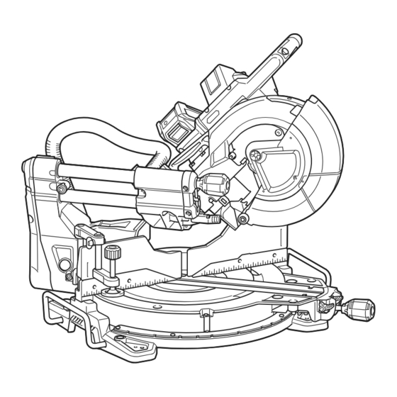
PARTS DESCRIPTION Knob (for bevel angle) Adjusting screw (for Adjusting bolt (for maxi- Hex wrench lower limit position) mum cutting capacity) Lock-off button Lid (for wireless unit) Stopper arm Switch trigger Hole for padlock Wireless activation Wireless activation lamp Lamp button button Vacuum button Blade case... -
Page 10: Installation
Handle Battery cartridge Dust bag (when replaced Hose (for dust extraction) with dust extraction hose) 0° adjusting bolt (for Pointer (for bevel angle) 45° adjusting bolt (for Bevel angle scale bevel angle) bevel angle) Latch lever (for bevel Releasing lever (for 48° Guide fence (upper Guide fence (lower angle) -
Page 11: Bench Mounting
To remove the sleeve of the hose from the port, pull the Installing and removing dust sleeve while pressing the stopper buttons on both sides extraction hose of the port. Attach the hose elbow to the upper port with the lock button facing upwards. -
Page 12: Functional Description
This tool should be bolted with four bolts to a level and stable surface using the bolt holes provided in the tool's base. This will help prevent tipping and possible injury. ► 1. Bolts ► 1. Red indicator 2. Button 3. Battery cartridge WARNING: Ensure that the tool will not move on the supporting surface. -
Page 13: Overdischarge Protection
Overdischarge protection Handle lock When the battery capacity becomes low, the tool stops automatically. If the tool does not run along with the CAUTION: Always hold the handle when switch operation, remove the battery from the tool and releasing the stopper pin. Otherwise the handle springs up and it may result in personal injury. -
Page 14: Blade Guard
WARNING: Do not remove spring holding blade guard. If guard becomes damaged in course of time or UV light exposure, contact a Makita ser- ► 1. Blade guard vice center for replacement. DO NOT DEFEAT OR REMOVE GUARD. Cleaning... - Page 15 NOTE: The rear screws can easily be loosened and NOTICE: When changing bevel angles, be sure tightened by turning the turn base at an angle. Make to reposition the kerf boards appropriately. sure to raise the handle fully when turning the turn NOTICE: Always remove the upper guide fences base.
- Page 16 Push the carriage toward the guide fences fully Rotate the blade by hand while holding the handle and lower the handle completely. all the way down to be sure that the circular saw blade does not contact any part of the lower base. Re-adjust slightly, if necessary.
-
Page 17: Adjusting The Miter Angle
Tighten the grip. Always hold the handle firmly CAUTION: when adjusting. Failure to do so may cause the carriage to jump up and result in injury. Adjusting the miter angle CAUTION: After changing the miter angle, always secure the turn base by returning the lock/ releasing lever to a locked position and tightening the grip firmly. - Page 18 Tighten the knob clockwise to secure the carriage Tilting the circular saw blade to the arm. left Rotate the knob on the slide pole counterclockwise. ► 1. Knob Pull and raise the latch lever up to allow free movement of the carriage arm. ►...
- Page 19 Tilting the circular saw blade to the Tilting the circular saw blade using right positive stop function Rotate the knob on the slide pole This miter saw employs positive stop function. You can counterclockwise. set 22.5° and 33.9° angle to both right and left quickly. Hold the handle and tilt the carriage to the left Rotate the knob on the slide pole slightly.
-
Page 20: Switch Action
A switch in need of repair may result in unintentional operation and serious personal injury. Return tool to a Makita service center for proper repairs BEFORE further usage. ► 1. Switch trigger 2. Lock-off button 3. Hole for ►... -
Page 21: Soft Start Feature
CAUTION: Do not touch the lens of the lamp a Makita service center. as it is very hot while it is lighted or shortly after it is turned off. This may cause burns. -
Page 22: Removing And Installing Saw Blade
Accidental start up of the tool may result in serious personal injury. WARNING: Use only the Makita wrench pro- vided to remove and install the circular saw blade. Failure to use the wrench may result in overtightening or insufficient tightening of the hex socket bolt and serious personal injury. -
Page 23: Installing The Blade
If the inner flange is removed, install it on the spindle with Mount the circular saw blade carefully onto the its recessed side facing the circular saw blade. If the flange is inner flange. Make sure that the direction of the arrow installed incorrectly the flange will rub against the machine. - Page 24 Connecting a vacuum cleaner When you wish to perform clean cutting operation, con- nect a Makita vacuum cleaner to the dust nozzle (upper dust port) using a front cuff 24 (optional accessory). ► 1. Front cuff 24 2. Hose 3. Vacuum cleaner ►...
-
Page 25: Securing Workpiece
Use upper fences to support the material higher than Securing workpiece the lower fences. Insert the upper fence into the hole on the lower fence and tighten the clamping screw. WARNING: It is extremely important to always secure the workpiece correctly with the proper type of vise or crown molding stoppers. - Page 26 Vertical vise NOTE: For a quick setting of workpiece, turning the vise knob to 90° counterclockwise allows the vise knob to be moved up and down. To secure the work- WARNING: The workpiece must be secured piece after setting, turn the vise knob clockwise. firmly against the turn base and guide fences with the vise during all operations.
- Page 27 Holders Sub base Optional accessory WARNING: Always support a long workpiece so it is level with the top surface of the turn base WARNING: Always support a long workpiece for an accurate cut and to prevent dangerous loss so it is level with the top surface of the turn base of tool control.
-
Page 28: Operation
Makita genuine saw blades, following materials can also be sawed : — Aluminum products Refer to our website or contact your local Makita dealer for the correct circular saw blades to be used for the material to be cut. WARNING: Make sure the saw blade is not contacting the workpiece, etc. -
Page 29: Miter Cutting
Slide (push) cutting (cutting wide Miter cutting workpieces) Refer to the section for adjusting the miter angle. Bevel cutting WARNING: Whenever performing a slide cut, first pull the carriage full towards you and press the handle all the way down, then push the car- WARNING: After setting the blade for a bevel riage toward the guide fence. -
Page 30: Compound Cutting
Compound cutting Compound cutting is the process in which a bevel angle is made at the same time in which a miter angle is being cut on a workpiece. Compound cutting can be performed at the angle shown in the table. Miter angle Bevel angle Left and Right 0°... - Page 31 In the case of left bevel cut In the case of right bevel cut (a) (b) (c) (d) (a) (b) (c) (d) 1. Inside corner 2. Outside corner 1. Inside corner 2. Outside corner Table (A) Table (A) – Molding Bevel angle Miter angle –...
- Page 32 Position crown molding with its WALL CONTACT EDGE Crown molding stopper against the guide fence and its CEILING CONTACT Optional accessory EDGE against the crown molding stoppers as shown in the figure. Adjust the crown molding stoppers according Crown molding stoppers allow easier cuts of crown to the size of the crown molding.
-
Page 33: Groove Cutting
After adjusting the lower limit position of the circu- Cutting aluminum extrusion lar saw blade, cut parallel grooves across the width of the workpiece using a slide (push) cut. ► 1. Cut grooves with blade Remove the workpiece material between the grooves with a chisel. - Page 34 Installing the wireless unit CAUTION: Always secure all moving portions before carrying the tool. If portions of the tool move Optional accessory or slide while being carried, loss of control or balance may occur and result in personal injury. Place the tool on a flat and stable CAUTION: CAUTION: Be sure that the carriage elevation...
- Page 35 Tool registration for the vacuum cleaner NOTE: A Makita vacuum cleaner supporting the wireless activation function is required for the tool registration. NOTE: Finish installing the wireless unit to the tool before starting the tool registration.
- Page 36 Set the stand-by switch on the vacuum cleaner to NOTE: The wireless activation lamps finish blinking "AUTO". in green after 20 seconds elapsed. Press the wireless activation button on the tool while the wireless acti- vation lamp on the cleaner is blinking. If the wireless activation lamp does not blink in green, push the wire- less activation button briefly and hold it down again.
- Page 37 NOTE: The wireless activation lamp on the tool will stop blinking in blue when there is no operation for 2 hours. In this case, set the stand-by switch on the vacuum cleaner to "AUTO" and push the wireless activation button on the tool again. NOTE: The vacuum cleaner starts/stops with a delay.
- Page 38 If the cancellation is performed successfully, the wire- Cancelling tool registration for the less activation lamps will light up in red for 2 seconds vacuum cleaner and start blinking in blue. NOTE: The wireless activation lamps finish blinking in Perform the following procedure when cancelling the red after 20 seconds elapsed.
- Page 39 Before asking for repairs, conduct your own inspection first. If you find a problem that is not explained in the manual, do not attempt to dismantle the tool. Instead, ask Makita Authorized Service Centers, always using Makita replace- ment parts for repairs.
-
Page 40: Maintenance
Push the carriage towards the guide fences and lock the sliding movement with the stopper pin. Lower the be performed by Makita Authorized or Factory Service carriage fully and lock it in the lowered position with Centers, always using Makita replacement parts. - Page 41 Carefully square the side of the circular saw blade with If the pointer does not indicate the 45° position, align it with the 45° position by turning the adjusting bolt in the the top surface of the turn base using the triangular rule, try-square, etc.
-
Page 42: After Use
OPTIONAL ACCESSORIES WARNING: These Makita accessories or attachments are recommended for use with your Makita tool specified in this manual. The use of any other accessories or attachments may result in serious personal injury. WARNING: Only use the Makita accessory or attachment for its stated purpose. - Page 44 Jan-Baptist Vinkstraat 2, Makita Europe N.V. 3070 Kortenberg, Belgium 3-11-8, Sumiyoshi-cho, Makita Corporation Anjo, Aichi 446-8502 Japan 885893A220 www.makita.com 20210323...
Need help?
Do you have a question about the LS004GZ and is the answer not in the manual?
Questions and answers