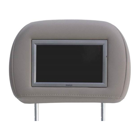
Vizualogic VL9000 Series Installation Manual
Headrest monitor system
Hide thumbs
Also See for VL9000 Series:
- Owner's manual (6 pages) ,
- Owner's manual (6 pages) ,
- Owner's manual (18 pages)
Advertisement
Quick Links
Download this manual
See also:
Owner's Manual
12 V Power Installation
We recommend the installation of a main power switch for the entire head-
rest system. The circuit should be marked to assist the consumer in locating
the correct vehicle fuse for the video system in the case of a system failure.
Vizualogic
®
Headrest System Diagram
- See diagram insert or go to www.vizualogic.com.
VL9000 Series
HEADREST MONITOR SYSTEM
Copyright © 2003 TMI Products, Inc.
All Rights Reserved
Installation Manual
Corona, CA U.S.A.
060300
1493 Bentley Drive • Corona, CA 92879 • 909-272-1996 • 800-624-7960 • Fax 909-272-1584
Fall 2003
www.vizualogic.com
99-8018-002
10/03
Advertisement

Summary of Contents for Vizualogic VL9000 Series
- Page 1 Vizualogic ® Headrest System Diagram - See diagram insert or go to www.vizualogic.com. VL9000 Series HEADREST MONITOR SYSTEM Copyright © 2003 TMI Products, Inc. All Rights Reserved Installation Manual Corona, CA U.S.A.
- Page 2 3. Hook end of headrest cable to the top of the “fishing tool” and pull cables through the seat. 4. Insert Vizualogic headrest in into post guide tubes. Now the headrest is secure. 5. Route headrest cable under the seat to the location of the A/V Controller. Be sure to secure your wires and allow enough slack for seat travel on the tracks.


Need help?
Do you have a question about the VL9000 Series and is the answer not in the manual?
Questions and answers