
Related Manuals for MCZ SELECTA 35 HQ S1


Summary of Contents for MCZ SELECTA 35 HQ S1
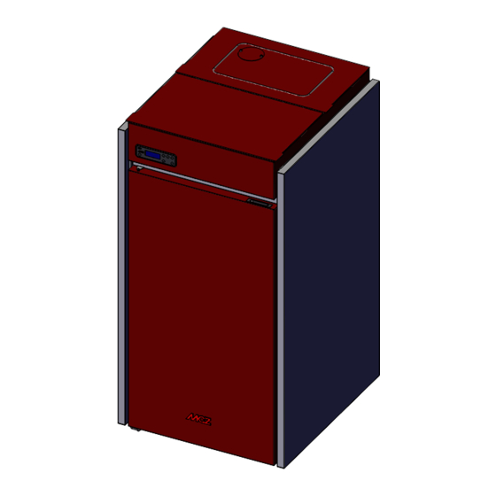
- Page 1 INSTALLATION GUIDE PELLET BOILER SELECTA 35 HQ S1 PART 1 - REGULATIONS AND ASSEMBLY Instructions in English...
-
Page 2: Table Of Contents
TABLE OF CONTENTS TABLE OF CONTENTS ....................II INTRODUCTION ......................1 1-WARNINGS AND WARRANTY CONDITIONS ..............2 2-INSTALLATION ......................9 3-DRAWINGS AND TECHNICAL CHARACTERISTICS............19 4-UNPACKING ......................22 5 - POSITIONING .......................24 6 - INSTALLATION AND DISASSEMBLY .................25 7-HYDRAULIC CONNECTION ..................32 8 - ELECTRICAL CONNECTION ..................39 9-WI-FI APPLICATION ....................40 II II... -
Page 3: Introduction
REVISIONS TO THE PUBLICATION The content of this manual is strictly technical and the property of MCZ. No part of this manual may be translated into other languages, adapted or reproduced, even in part, in other mechanical or electronic forms, photocopies, recordings or other, without the prior written authorisation from MCZ. -
Page 4: 1-Warnings And Warranty Conditions
1-WARNINGS AND WARRANTY CONDITIONS SAFETY PRECAUTIONS • Installation, electrical connection, function test and maintenance must only be carried out by authorised and qualified personnel. • Install the product in accordance with all local and national legislation and regulations in force in the region or country. • Bad use or improper maintenance of the product can bring to a serious risk of explosion in the combustion chamber. - Page 5 1-WARNINGS AND WARRANTY CONDITIONS parts could be hazardous for the operator’s safety and relieves the company of any civil and criminal liability. • Many of the surfaces of the product get very hot (door, handle, glass, smoke outlet pipes, etc.). Avoid coming into contact with these parts, without adequate protective clothing or suitable implements, such as gloves with thermal protection or “cold handle”...
- Page 6 1-WARNINGS AND WARRANTY CONDITIONS • Do not light the stove with flammable materials if the ignition system breaks down. • Do not stand for a long time in front of the product in operation. Do not overheat the room you are in and where the product is installed. This could cause injuries and health problems.
- Page 7 1-WARNINGS AND WARRANTY CONDITIONS INFORMATION • If there are any issues, contact the retailer or a qualified technician authorised by MCZ. In the event of a repair, request the use of original spare parts. • Only use types of fuel recommended by MCZ (for Italy, pellets with a 6 mm diameter and pellets with a 6-8 mm diameter for other European countries), which must only be loaded with an automatic feed system.
- Page 8 1-WARNINGS AND WARRANTY CONDITIONS WARRANTY CONDITIONS The firm covers the product,with the exception of the parts prone to normal wear that are listed below, for a period of 2 (two) years from the date of purchase as proved by: • a document to serve as proof of purchase (invoice and/or receipt) that shows the name of the vendor and the date on which the purchase was made;...
- Page 9 1-WARNINGS AND WARRANTY CONDITIONS Any technical interventions on the product to eliminate the above defects and consequent damage must be agreed upon with the Service Centre, who reserves the right to accept the relative appointment or not. However, said interventions will not be carried out under warranty but as technical assistance to be granted as part of any eventual and specific agreed conditions and in accordance with the fee in force for the work to be carried out.
- Page 10 1-WARNINGS AND WARRANTY CONDITIONS RULES FOR INSTALLATION The product is a boiler that uses wood pellets. Below are some reference European standards for product installation: EN 303-5:2012: Solid fuel boilers, with manual or automatic loading, nominal thermal power of 500 kW - Terminology, requisites, tests and marking.
-
Page 11: 2-Installation
2-INSTALLATION The instructions in this chapter refer explicitly to the Italian installation regulation UNI 10683. In any case, always observe the regulations in force in the country of installation. PELLETS Wood pellets are manufactured by hot-extruding compressed sawdust which is produced during the working of natural dried wood. The compactness of the material is guaranteed by the lignin contained in the wood itself and allows pellets to be produced without glue or binders. - Page 12 2-INSTALLATION PRECAUTIONS REGARDING INSTALLATION IMPORTANT! Product installation and assembly must be carried out by qualified personnel. The product must be installed in a suitable place that allows easy access for it to be opened regularly and for routine maintenance to be performed.
- Page 13 2-INSTALLATION POSITIONING AND RESTRICTIONS In the case of simultaneous installation with other heating appliances, provide appropriate air inlets for each one (according to the instructions of each product). Installation of the product is not permitted: • in rooms where there are liquid fuel appliances with continuous or intermittent operation that draw the combustion air from the room they are installed in;...
- Page 14 2-INSTALLATION FOREWORD The Flue chapter has been drawn up with reference to the provisions of European Standards (EN13384 - EN1443 - EN1856 - EN1457). The chapter provides indications for installing an efficient and correct flue but is under no circumstances to substitute the regulations in force, which the qualified technician must be in possession of.
- Page 15 2-INSTALLATION TECHNICAL CHARACTERISTICS Flues serving a pellet/wood fuelled appliance must meet the following requirements: • be made of materials that are sufficiently resistant to mechanical stress, heat, the action of the products of combustion and their vapours. • be made of materials that are impermeable to fumes, condensation, be thermally insulated and resistant to normal mechanical stress over time •...
- Page 16 2-INSTALLATION ROOF AT 30° A = MIN. 1.30 metres B = DISTANCE > 1.50 metres C = DISTANCE < 1.50 metres D = 0.50 metres ABOVE HIGHEST POINT E = 0.80 metres F = REFLUX AREA 30° FIGURE 4 ROOF AT 60° A = MIN.
- Page 17 2-INSTALLATION SIZING The negative pressure (draught) of a flue depends on its height. Check the negative pressure with the values indicated in the technical characteristics. The minimum height of the chimney is 3.5 metres. The interior cross-section of the flue can be round (best), square or rectangular (the ratio between the internal sides must be ≤1.5) with the sides joined with a minimum radius of 20 mm.
- Page 18 2-INSTALLATION MAINTENANCE The flue must be kept clean, since the deposit of soot or unburnt oils reduces the cross-section reducing the draught and thus compromising the efficient operation of the stove and, if large build-ups accumulate, can catch fire. The flue and chimneypot must be cleaned and checked by a qualified chimney sweep at least once a year.
- Page 19 2-INSTALLATION CONNECTION TO THE FLUE The connection between the flue and the appliance must be via a smoke duct that complies with EN 1856-2. The connecting section must extend no more than 4 m horizontally, with a minimum slope of 3% and with a maximum of 3 90% bends (accessible for inspection - do not count the Tee fitting at the appliance outlet).
- Page 20 2-INSTALLATION EXAMPLES OF CORRECT INSTALLATION 1. Installation of Ø150mm flue with hole for the passage of the pipe increased by: minimum 100mm around the pipe if next to non flammable parts such as cement, brick, etc.; or minimum 300mm around the pipe (or as required by rating plate) if next to flammable parts such as wood etc.
-
Page 21: 3-Drawings And Technical Characteristics
3-DRAWINGS AND TECHNICAL CHARACTERISTICS DRAWINGS AND CHARACTERISTICS SELECTA 35 HQ S1 DIMENSIONS (dimensions in mm) Ø80 Ø100 218.5 Ø100 Technical Dept. - All rights reserved - Reproduction prohibited... - Page 22 3-DRAWINGS AND TECHNICAL CHARACTERISTICS TECHNICAL CHARACTERISTICS SELECTA 35 HQ S1 Energy Efficiency Class Product class (EN 303-5/2012) Rated thermal capacity of the firebox 34.1 kW (29326 kcal/h) Nominal output power: 31.7 kW (27262 kcal/h) Minimum output power 7.2 kW (6192 kcal/h) Efficiency at Max 92.8%...
- Page 23 3-DRAWINGS AND TECHNICAL CHARACTERISTICS TECHNICAL DOCUMENTATION FOR SOLID FUEL BOILERS ACCORDING TO COMMISSION REGULATIONS (EU) 2015/1187 - (EU) 2015/1189 Manufacturer: MCZ GROUP S.p.A. Trademak: Model Identifier: SELECTA 35HQ S1 General description: Solid Fuel Boiler fired by wood pellets Condensing Boiler:...
- Page 24 3-DRAWINGS AND TECHNICAL CHARACTERISTICS TECHNICAL DOCUMENTATION FOR SOLID FUEL BOILERS ACCORDING TO COMMISSION REGULATIONS (EU) 2015/1187 - (EU) 2015/1189 Manufacturer: MCZ GROUP S.p.A. Trademak: Model Identifier: SELECTA 35HQ ACS S1 General description: Solid Fuel Boiler fired by wood pellets Condensing Boiler:...
- Page 25 3-DRAWINGS AND TECHNICAL CHARACTERISTICS RESIDUAL PRESSURE HEAD WITH DHW KIT CHART 1000 B = FLOW RATE (dm3/h) A = Residual pressure head (mbar) B = Flow rate (l/h) RESIDUAL PRESSURE HEAD WITHOUT DHW KIT CHART 1000 1050 1100 B = FLOW RATE (dm3/h) Technical Dept.
-
Page 26: 4-Unpacking
4-UNPACKING PREPARATION AND UNPACKING The boiler is delivered complete with all its electrical, mechanical, and hydraulic components after it has been tested in the factory: Remove the cardboard, remove the brackets that secure the boiler to the pallet as well as the polystyrene. To remove the rear bracket (fig.2) one must remove the three screws “x”... - Page 27 4-UNPACKING To remove the front bracket (fig.3) proceed as follows: • open the door • remove the screws “x” • remove the screws “y” • extract the bracket “s” Figure 3 - Front bracket removal Install the boiler in the area set aside for it, making sure it conforms to the requirements. The boiler body or unit must always be kept in a vertical position when moved, and only using suitable lifting trolleys.
-
Page 28: Positioning
5 - POSITIONING REQUIREMENTS FOR INSTALLATION OF THE PLANT - POSITIONING The most important thing to do before installation of the boiler is to set aside a suitable area that meets the minimum requirements for installation. • the minimum clearance in front of the product for the purpose of cleaning, maintenance, etc. must be 700 mm; •... -
Page 29: Installation And Disassembly
6 - INSTALLATION AND DISASSEMBLY FUMES EXHAUST AND COMBUSTION AIR INLET The boiler is fitted at the back with a pipe “U” 0100 mm for fumes exhaust and with a pipe “E” 0 80 mm for combustion air inlet. Technical Dept. - All rights reserved - Reproduction prohibited... - Page 30 6 - INSTALLATION AND DISASSEMBLY BOILER DOORS OPENING/CLOSING ATTENTION! The door must be closed properly for the boiler to work correctly. The firebox door and the lower door for cleaning the ash must only be opened with the boiler cold and off. If the doors are opened while the boiler is running, a system will trigger the alarm and the boiler will go off.
- Page 31 6 - INSTALLATION AND DISASSEMBLY ACCESS TO THE ELECTRONIC BOARD To have access to the electronic board, you must remove the right decoration panel (door opening side) according to the indications in this manual. 29 29 Technical Dept. - All rights reserved - Reproduction prohibited...
- Page 32 6 - INSTALLATION AND DISASSEMBLY REAR COVER FOR THE HYDRAULIC KIT The back of the boiler has a removable cover to insert the selected hydraulic kit. Remove cover “R” by loosening the two upper screws and lifting the cover so as to release the joint “u” of the cover from the “v” joint of the boiler. REAR PANEL REMOVAL For interventions on the boiler components one may need to remove the rear panel “O”.
- Page 33 6 - INSTALLATION AND DISASSEMBLY SIDE PANEL REMOVAL To remove the side panels proceed as follows: • At the rear, remove the two screws “x” Technical Dept. - All rights reserved - Reproduction prohibited...
- Page 34 6 - INSTALLATION AND DISASSEMBLY • on the front, open the decorative door “F” • remove the two screws “w”...
- Page 35 6 - INSTALLATION AND DISASSEMBLY • lift panel “C” so that hook “k” comes out from slot “v” on the boiler’s structure. Technical Dept. - All rights reserved - Reproduction prohibited...
-
Page 36: 7-Hydraulic Connection
7-HYDRAULIC CONNECTION HYDRAULIC CONNECTION IMPORTANT: The connections depend on the type of System Configuration. IMPORTANT! If installing the boiler involves another pre-existing system complete with heating equipment (gas boiler, methane boiler, fuel oil boiler, etc.), it is strongly recommended that you contact a qualified operator who subsequently will be responsible for the compliance of the system with the applicable laws in force. - Page 37 7-HYDRAULIC CONNECTION CONNECTION WITH HYDRAULIC KIT FOR DOMESTIC HOT WATER PRODUCTION DIAGRAM (SEE ACCESSORY CODE 40A18014) 2 - SAFETY VALVE 5 - DOMESTIC HOT WATER INLET 3 - FILLING TAP 6 - HEATING RETURN 4 - DOMESTIC HOT WATER OUTLET 7 - HEATING DELIVERY Technical Dept.
- Page 38 7-HYDRAULIC CONNECTION SAFETY VALVE 3 bar (300Pa) The boiler is protected against overpressure by a safety valve “2” fitted on the selected hydraulic kit. The safety valve drain must be connected to a rubber pipe that can withstand a temperature of 110°C (not supplied) and that reaches the outside via an anti-odour syphon.
- Page 39 7-HYDRAULIC CONNECTION CLEANING THE SYSTEM Install suitable shutters to cut off the tubes from the heating system. In order to protect the heating system from damage caused by corrosion, incrustation or deposit build-up, it is important to clean the appliance before installation, using suitable products, in compliance with Standard UNI 8065 (water treatment of thermal plants for civil use).
- Page 40 7-HYDRAULIC CONNECTION • after starting up the boiler for the first time and bringing the system up to temperature, stop the pumps and repeat the air purging procedure; • leave the system to cool, and if necessary, restore the water pressure to 1 bar (100 Pa). NOTE In systems with a closed vessel, where possible, the water pressure in the heating system must not be lower than 1 bar (100 Pa) when the system is at room temperature;...
- Page 41 A higher return temperature reduces the formation of condensation of the fumes and extends the life of the boiler. Valves available on the market offer various calibrations. MCZ recommends using the model (see accessories list) at 55°C. The thermostatic sensor immersed directly in the fluid “feels” the temperature and diverts the route according to the required value (55°C).
- Page 42 7-HYDRAULIC CONNECTION PRESSURE GAUGE The pressure gauge of the boiler “m” is one of the key tools, which is used to check that the appliance is operating smoothly. The pressure gauge of the boiler is used to measure the pressure, i.e. the difference between the internal pressure and the atmospheric pressure. Generally, the ideal pressure for a boiler is between 1.5 and 2 bar (150-200 Pa), above or below which malfunctions occur in the heating system or in the supply of domestic hot water.
-
Page 43: Electrical Connection
8 - ELECTRICAL CONNECTION GENERAL PRECAUTIONS The electrical safety of the system is guaranteed only when this is connected correctly to an efficient earthing system installed in accordance with the safety standards in force: the pipes of the gas, water and heating systems do not constitute a suitable earth system. It is necessary to ensure this essential safety requirement;... -
Page 44: 9-Wi-Fi Application
9-WI-FI APPLICATION WIFI PANEL (EASY CONNECT) The Easy Connect WiFi panel is already installed at the back of the stove and connected to the board. In order to use the WiFi system, the customer must download the app and follow the set-up instructions. EXAMPLE OF EASYCONNECT MODULE SILVER LABEL APPLICATION INSTALLATION AND CONFIGURATION... - Page 45 9-WI-FI APPLICATION The product set up procedure consists of 5 basic steps: 1 - APP INSTALLATION You can download the app with one of the following methods: - Scan the QR Code on the label of the Wi-Fi module - Search for the app’s name given on the label on the store for your smartphone 2 - USER REGISTRATION a) At first login confirm all the authorisations required by the app.
- Page 46 9-WI-FI APPLICATION Stove serial number On the stove’s warranty card and inside the pellet hopper. MAC address Found on the label on the “ET” page inside the document envelope inside the store. Registration Code (Reg.Code) Found on the label on the “ET” page inside the document envelope inside the store.
- Page 47 9-WI-FI APPLICATION 5 - USING THE APP 1. When the “plug” appears next to the added stove, it means that the stove is connected. You can now use the app. 2. To open the stove controls, tap on the stove name in the “My stoves” list. 3.
- Page 48 Via La Croce n°8 33074 Vigonovo di Fontanafredda (PN) – ITALY Telephone: 0434/599599 a.s. Fax: 0434/599598 Website: www.mcz.it e-mail: info.red@mcz.it 8902111700 REV. 1 27/08/2021...
- Page 49 INSTALLATION GUIDE PELLET BOILER SELECTA 35 HQ S1 PART 2 - OPERATION AND CLEANING Instructions in English...
- Page 50 TABLE OF CONTENTS TABLE OF CONTENTS ....................2 10- FIRST START-UP ....................3 11 - MENU ITEMS AND FUNCTION .................7 12 - SAFETY DEVICES AND ALARMS ................22 13-RECOMMENDATIONS FOR SAFE USE ...............27 14 - MAINTENANCE AND CLEANING ................28 15 - TROUBLESHOOTING ....................36 16 - WIRING DIAGRAM ....................39...
-
Page 51: 10- First Start-Up
10- FIRST START-UP BEFORE START-UP GENERAL PRECAUTIONS Remove all parts that may burn from the brazier and the product’s tank (manual, various adhesive labels or any polystyrene). The first start-up may not be successful as the feed screw is empty and does not always manage to load the brazier with the required amount of pellets in time to light the flame. - Page 52 10 - FIRST START-UP SETTINGS TO BE CARRIED OUT BEFORE THE INITIAL START-UP After connecting the power cable to the electrical socket, turn the power switch to the (I) position. To turn the boiler on or off, press button 1 on the control panel for a few seconds. Switch-on is signalled on the display by the text ON and the flame icon flashing.
- Page 53 10 - FIRST START-UP LOADING THE PELLETS The pellets can be loaded either manually or automatically. The empty tank can contain up to 100 litres or 65 kg of pellets. Manual Loading: • Open the top door “C” of the boiler directly and pour in the pellets. Automatic loading (with remote tank of 200/400 or 300 kg - optional - see accessories): Remove the “V”...
- Page 54 10 - FIRST START-UP SAFETY WHAT TO DO IF SMOKE LEAKS INTO THE ROOM OR IN CASE OF EXPLOSION DAMAGING THE DEVICE: SWITCH IT OFF, VENTILATE THE ROOM AND IMMEDIATELY CONTACT THE INSTALLER/TECHNICIAN IN CHARGE OF ASSISTANCE. User Training In ALL cases, the technician in charge of installation and first-start-up MUST carry out a thorough handover of the appliance to the owner / end user.
-
Page 55: Menu Items And Function
11 - MENU ITEMS AND FUNCTION CONTROL PANEL DISPLAY Menu options 1. Switching boiler on/off 5. Decrease set temperature / programming functions. 2. Scrolling down through the programming menu 6. Increase set temperature / programming functions. 3. Menu 7. Display. 4. - Page 56 11 - MENU ITEMS AND FUNCTION PROGRAMMED MODE (TIMER) - Main menu The current time and date must be configured to ensure correct operation of the timer. There are six configurable TIMERS; for each one, the user can select a start and stop time and the days of the week when it is in use. When one or more programs are active, the status of the boiler and the TIMER “n”...
- Page 57 11 - MENU ITEMS AND FUNCTION NOTES ON USE OF THE TIMER • The timer always starts the boiler with the last temperature and ventilation settings (or with the default settings at 20°C and V3 if they have never been altered). •...
- Page 58 11 - MENU ITEMS AND FUNCTION SETTINGS MENU The SETTINGS menu is for configuring use of the boiler: a. Language. b. Cleaning (shown only when boiler is off). Load feed screw (shown only when boiler is off). d. Tones. e. External thermostat (activation). Auto Eco (activation).
- Page 59 11 - MENU ITEMS AND FUNCTION c - Load feed screw This is for filling the pellet loading system. This can be enabled only when the boiler is off. A 180” countdown appears. The feed screw stops automatically at the end of the countdown and the menu closes. To select “Load feed screw”...
- Page 60 11 - MENU ITEMS AND FUNCTION • Use the + - keys to select “On”. • Press “menu” to confirm and “esc” to exit. g - Eco Switch-off T To select the Eco Stop T function, proceed as follows: • Press the “menu”...
- Page 61 11 - MENU ITEMS AND FUNCTION i - Auxiliary boiler An additional module (optional) must be installed to allow the start-up of an auxiliary boiler when the main boiler is off or has been stopped due to an alarm. The default settings have this function disabled. To enable the function, go to the settings menu. l - Pellet Recipe This function is for adapting the boiler to the type of pellet in use.
- Page 62 11 - MENU ITEMS AND FUNCTION l - Maximum power Allows you to set the maximum power limit of the flames which the boiler can use to reach the set target temperature. Modify the power as follows: • Press the “menu” key. •...
- Page 63 11 - MENU ITEMS AND FUNCTION o - System configuration This function allows you to set the type of hydraulic system that the product must manage. To change the configuration of the system, proceed as follows: • Press the “menu” key. •...
- Page 64 11 - MENU ITEMS AND FUNCTION SYSTEM CONFIGURATIONS At the time of installation, the product must be configured according to the type of system by selecting the relative parameter in the “SETTINGS” menu. There are 5 possible configurations, described below: Configuration Description Room temperature control via boiler's on-board probe or by enabling external thermostat FACTORY SETTING...
- Page 65 11 - MENU ITEMS AND FUNCTION CONFIGURATION 2 CONFIGURATION 3 Technical Dept. - All rights reserved - Reproduction prohibited...
- Page 66 11 - MENU ITEMS AND FUNCTION CONFIGURATION 4...
- Page 67 11 - MENU ITEMS AND FUNCTION CONFIGURATION 5 SELECTA 35Q S1 HEATING DELIVERY HEATING RETURN ZONE VALVE HEATING BODIES DOMESTIC HOT WATER DOMESTIC COLD WATER DOMESTIC HOT WATER STORAGE CYLINDER DIVERTER VALVE STORAGE CYLINDER THERMOSTAT THERMOSTATIC MIXER VALVE NTC PROBE 10 kΩ β3434 DOMESTIC HOT WATER HEATING PUFFER HEATING SYSTEM CIRCULATOR PUFFER THERMOSTAT...
- Page 68 11 - MENU ITEMS AND FUNCTION OPERATING MODE The operating mode for boilers is always AUTOMATIC (there is no manual operating mode available). Flame regulation is controlled according to the “System configuration” by the room temperature probe, by the external thermostat, by the temperature of the water in the boiler or by the NTC probes.
- Page 69 11 - MENU ITEMS AND FUNCTION START-UP Press key 1 (esc) to start up the appliance. The display will show ON with the flashing flame symbol. When the flame stops blinking, the boiler has reached the operating condition for the “power supply”. The default target room temperature is set at 20°C.
-
Page 70: Safety Devices And Alarms
12 - SAFETY DEVICES AND ALARMS SAFETY DEVICES The product is fitted with the following safety devices PRESSURE SWITCH Monitors pressure in the smoke duct. It is designed to shut down the pellet feed screw in the event of an obstructed flue or significant back-pressure (from the wind). - Page 71 12 - SAFETY DEVICES AND ALARMS TAMPERING WITH THE SAFETY DEVICES IS PROHIBITED If the product is NOT used as described in this instruction manual, the manufacturer declines all liability for any damage caused to persons and property. In particular: •...
- Page 72 12 - SAFETY DEVICES AND ALARMS ALARM SIGNALLING When a condition occurs other than the one expected for regular operation of the boiler, an alarm is triggered. The reason for the alarm is given on the control panel. The sound signal is not enabled for alarms A01-A02 in order not to disturb the user when there is an absence of pellets in the tank during the night.
- Page 73 12 - SAFETY DEVICES AND ALARMS ALARM A05 TRIGGERED A bracket “s” is fastened below the door of the firebox “E” preventing the lower door “J” from opening if the firebox door “E” is closed. The firebox door “E” has a control device that blocks operation of the boiler if the door remains open. The alarm A05 is activated.
- Page 74 12 - SAFETY DEVICES AND ALARMS ALARM RESET NEVER open the stove door whilst it is either in the initial ignition or on its shut down cycle, pellets will still be smouldering or therefore volatiles may be present. ATTENTION! If during operation or initial ignition you encounter combustion smoke leakage into the room from the appliance or the flue, then please switch off the appliance, ventilate the room and contact the installation / service technician immediately.
-
Page 75: 13-Recommendations For Safe Use
13-RECOMMENDATIONS FOR SAFE USE ONLY CORRECT INSTALLATION AND APPROPRIATE MAINTENANCE AND CLEANING OF THE APPLIANCE CAN GUARANTEE CORRECT OPERATION AND SAFE USE OF THE PRODUCT We would like to inform you that we are aware of cases of malfunctioning of domestic pellet-fuelled heating products, mainly due to incorrect installation and inappropriate maintenance. -
Page 76: Maintenance And Cleaning
The automatic cleaning system means you don’t have to empty the brazier. However, if there are pellets with a very high ash residue this system may not be enough. We therefore recommend adjusting the checks to the kind of fuel you are using. MCZ recommends using A1 class pellets with an ash residue of less than 0.7%. - Page 77 14 - MAINTENANCE AND CLEANING CLEANING THE ASH PAN You must remove the ash pan “M” of the boiler and empty the ash at least every two weeks. To do so you must open the door of the boiler, open the lower door “J”, remove the ash pan “M” and empty it. Wipe away any ash residue and reinsert the pan. Also vacuum the lower compartment.
- Page 78 14 - MAINTENANCE AND CLEANING CLEAN THE HEAT EXCHANGER AND THE COMPARTMENT BENEATH THE BRAZIER EVERY 2/3 DAYS Cleaning the heat exchanger and the compartment beneath the brazier is a simple operation but very important if the boiler is to maintain optimal performance.
- Page 79 14 - MAINTENANCE AND CLEANING PERIODIC CLEANING PERFORMED BY A QUALIFIED TECHNICIAN CLEANING THE HEAT EXCHANGER AND PIPE UNIT CLEANING THE UPPER COMPARTMENT When the boiler has cooled down, lift the front cover “T”; undo the two screws “I” on the cover “H”. Remove the two screws “L” and take off the cover “H”...
- Page 80 14 - MAINTENANCE AND CLEANING CLEANING THE SMOKE EXTRACTOR COMPARTMENT In the area behind the ash pan “M”, there is the smoke cap “Q”, which must be removed to clean the smoke extractor. Therefore: • loosen the screws “s” • remove the smoke cap “Q”...
- Page 81 14 - MAINTENANCE AND CLEANING CLEANING THE SMOKE EXPULSION SYSTEM AND GENERAL CHECKS Clean the smoke outlet system, especially around the “Tee” fittings, elbows and any horizontal sections of the smoke duct. For information on periodically cleaning the flue, contact a skilled chimney sweep. If necessary, order new replacement gaskets from the retailer or contact an authorised service centre to carry out the operation.
- Page 82 14 - MAINTENANCE AND CLEANING REPLACING THE OVERPRESSURE DISCHARGE FOR THE COMBUSTION CHAMBER Overpressure rubber bushing “G” of the combustion chamber (fig. A) may get worn and/or damaged, it is therefore necessary to replace it once a year to ensure correct system operation. To replace it, follow the instructions below •...
- Page 83 14 - MAINTENANCE AND CLEANING CHECKING THE INTERNAL COMPONENTS ATTENTION! The internal electromechanical components must only be checked by qualified personnel whose technical expertise includes combustion and electricity. We recommend that an annual maintenance service is carried out (with a scheduled service contract). This service is essentially a visual and functional inspection of the internal components.
-
Page 84: Troubleshooting
15 - TROUBLESHOOTING CHECKING THE INTERNAL COMPONENTS ATTENTION: GUIDE FOR THE EXCLUSIVE USE OF THE SPECIALISED TECHNICIAN ATTENTION: All repairs must be carried out exclusively by a specialised technician, while the boiler is completely cold and the electric plug is disconnected. The operations in bold type must be carried out by specialised personnel. The manufacturer will not be liable and the guarantee is invalidated if this condition is not respected. - Page 85 15 - TROUBLESHOOTING ANOMALY POSSIBLE CAUSES SOLUTIONS The boiler runs for a few minutes and Ignition phase is not completed Repeat ignition then goes out. Temporary power cut Wait for the automatic restart Clogged smoke duct Clean the smoke duct Faulty or malfunctioning temperature Check and replace the probes probes...
- Page 86 15 - TROUBLESHOOTING The boiler does not run No power supply Check that the plug is inserted and the main switch is in the “I” position. Pellet probe stop Cancel stoppage by changing the setting of the rear thermostat. If the problem persists, request assistance.
-
Page 87: Wiring Diagram
16 - WIRING DIAGRAM MOTHERBOARD WIRING KEY FUSE 14. 3-WAY VALVE PHASE (DHW) BOARD PHASE 15. 3-WAY VALVE PHASE (HEATING) BOARD NEUTRAL 16. AUXILIARY BOILER CONNECTION (TERMINAL BLOCK) SMOKE EXTRACTOR 17. SMOKE PROBE ---------------------- 18. EXTERNAL THERMOSTAT CONNECTION (TERMINAL BLOCK) WATER SAFETY THERMOSTAT 19. - Page 88 Via La Croce n°8 33074 Vigonovo di Fontanafredda (PN) – ITALY Telephone: 0434/599599 a.s. Fax: 0434/599598 Website: www.mcz.it e-mail: info.red@mcz.it 8902111800 REV. 0 19/02/2021...
Need help?
Do you have a question about the SELECTA 35 HQ S1 and is the answer not in the manual?
Questions and answers