Table of Contents
Advertisement
Available languages
Available languages
Quick Links
Form No. 3316480.000 10/15
©2015 Dometic Corporation
LaGrange, IN 46761
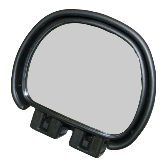
SPOT MIRROR
Read these instructions carefully. These
instructions MUST stay with this product.
USA
SERVICE OFFICE
Dometic Corporation
2320 Industrial Parkway
Elkhart, IN 46516
RECORD THIS INFORMATION FOR FUTURE
REFERENCE:
Model Number
Serial Number
Date Purchased
Retailer / Qualified Installer
AERO BLIND
DM-3100
CANADA
Dometic Corporation
46 Zatonski, Unit 3
Brantford, ON N3T 5L8
CANADA
SERVICE CENTER &
DEALER LOCATIONS
Please Visit:
www.eDometic.com
Advertisement
Table of Contents

Related Manuals for Dometic MILENCO DM-3100


Summary of Contents for Dometic MILENCO DM-3100
- Page 1 CANADA SERVICE CENTER & DEALER LOCATIONS SERVICE OFFICE Dometic Corporation Dometic Corporation 46 Zatonski, Unit 3 Please Visit: Form No. 3316480.000 10/15 2320 Industrial Parkway Brantford, ON N3T 5L8 www.eDometic.com ©2015 Dometic Corporation Elkhart, IN 46516 CANADA LaGrange, IN 46761...
-
Page 2: Document Symbols
DOCUMENT SYMBOLS I ndicates additional information that is NOT related I ndicates step-by-step instructions. to physical injury. IMPORTANT SAFETY INSTRUCTIONS Supplemental Directives This manual has safety information and instructions to help you eliminate or reduce the risk of accidents and injuries. ... -
Page 3: Installation
INSTALLATION Prepare for Installation FIG. 4 1. U sing a #2 Phillips screwdriver, remove pan head screw (4 mm x 20 mm) from mirror hous- ing. See (FIG. 2). FIG. 2 Heel Foot 2. Position blind spot mirror on vehicle mirror for maximum viewing. - Page 4 INSTALLATION FIG. 6 6. Installation is now complete. Removal 1. T o remove blind spot mirror from vehicle, refer to steps (1), (2) and (3) of “A. Prepare for Installa- tion” on page 3, allowing removal. DM-1953 Aero Pad Replacement 1.
- Page 5 CENTRES DE SERVICE SERVICE OFFICE Dometic Corporation Dometic Corporation 46 Zatonski, bureau 3 APRÈS-VENTE OU DES Formulaire n° 3316480.000 10/15 2320 Industrial Parkway Brantford, ON N3T 5L8 CONCESSIONNAIRES, ©2015 Dometic Corporation Elkhart, IN 46516 consulter : LaGrange, IN 46761 www.eDometic.com...
-
Page 6: Symboles Utilisés Dans Le Document
SYMBOLES UTILISÉS DANS LE DOCUMENT I nformations supplémentaires NON liées à des risques I nstructions étape par étape. de blessures. INSTRUCTIONS DE SÉCURITÉ IMPORTANTES Directives supplémentaires Ce manuel comporte des renseignements et des instructions sur la sécurité, destinés à permettre aux ... - Page 7 INSTALLATION Préparation de l’installation FIG. 4 1. À l’aide d’un tournevis Phillips n° 2, retirer la vis à tête cylindrique large (4 mm x 20 mm) du boîtier du rétroviseur (FIG. 2). FIG. 2 Talon Pied 2. Positionner le rétroviseur pour angle mort sur le rétroviseur du véhicule pour une visibilité...
- Page 8 INSTALLATION FIG. 6 6. L’installation est maintenant terminée. Dépose 1. P our retirer du véhicule, le rétroviseur pour angle mort, se reporter aux étapes 1., 2. et 3., de la section A. Préparation de l’installation, à la page 7. Remplacement de patin Aero DM-1953 1.
- Page 9 CENTRO DE SERVICIO Y LUGARES DE DISTRIBUCIÓN SERVICE OFFICE Dometic Corporation Dometic Corporation 46 Zatonski, Unit 3 Visite: Formulario No. 3316480.000 10/15 2320 Industrial Parkway Brantford, ON N3T 5L8 www.eDometic.com ©2015 Dometic Corporation Elkhart, IN 46516 CANADÁ LaGrange, IN 46761...
-
Page 10: Instrucciones Importantes De Seguridad
SÍMBOLOS DEL DOCUMENTO I ndica información adicional NO relacionada con I ndica instrucciones paso por paso. lesiones físicas. INSTRUCCIONES IMPORTANTES DE SEGURIDAD Instrucciones adicionales Este manual contiene información e instrucciones de seguridad destinadas a eliminar o reducir el riesgo de ... -
Page 11: Instalación
INSTALACIÓN Preparación FIG. 4 1. U tilizando el destornillador Phillips #2, retire el tonillo de cabeza plana (4 mm x 20 mm) de la caja del espejo Ver (FIG. 2). FIG. 2 Talón Pié 2. Coloque el retrovisor para punto ciego en el espejo del vehículo para lograr la mejor visión. - Page 12 INSTALACIÓN FIG. 6 FIG. 7 Ranura Pestaña Extremo esférico bloque Bloque de soporte Aero Rótula (Pieza No. DM-1953) 6. La instalación ya se ha finalizado. Desmontaje 1. P ara retirar el retrovisor punto ciego del vehículo, consulte los pasos (1), (2) y (3) de la sección “A.
Need help?
Do you have a question about the MILENCO DM-3100 and is the answer not in the manual?
Questions and answers