
Related Manuals for DAS 1221


Summary of Contents for DAS 1221
- Page 1 Model 1221 with Oscillation Indication DAS Public Safety Annunciator Panel Installation Instructions 12/01/2023 sales@dasalert.com Technical Support ph: 303 526 1965 8:am - 5:pm (Mountain)
-
Page 2: Table Of Contents
Contents Page Compatibility Main PC Board Included Items Connector and DIP Switch Locations LED Panel Indicators Self-Test Buzzer / Alarm DC Power for the Panel Wiring Options 6 -10 DIP Switch Settings 11-12 Panel AA Battery Backup Connections to Building’s Fire Panel Removal of Knockouts Relay and End-of-Line Resistor Connections to Fire Panel External Detection of Donor Antenna Disconnection... - Page 3 Contents - Figures and Tables Page Figure 1. Included Items Figure 2. Connector and DIP Switch Locations Figure 3. Wiring Diagram if cable length is less than 20 feet Figure 4. Wiring Diagram with two CAT 5/6 Cables Figure 5. Wiring Digram with one CAT 5/6 Cable Figure 6.
-
Page 4: Compatibility
Figure 2 shows the layout of the main PC board and the locations of the DIP switches (shown in factory default settings, and in Table 3). Figure 2 also shows connector locations that are connected to the DAS equipment and the building’s Fire Panel. - Page 5 Figure 1. Included Items - 2 -...
-
Page 6: Connector And Dip Switch Locations
Figure 2. Connector and DIP Switch Locations - 3 -... -
Page 7: Led Panel Indicators
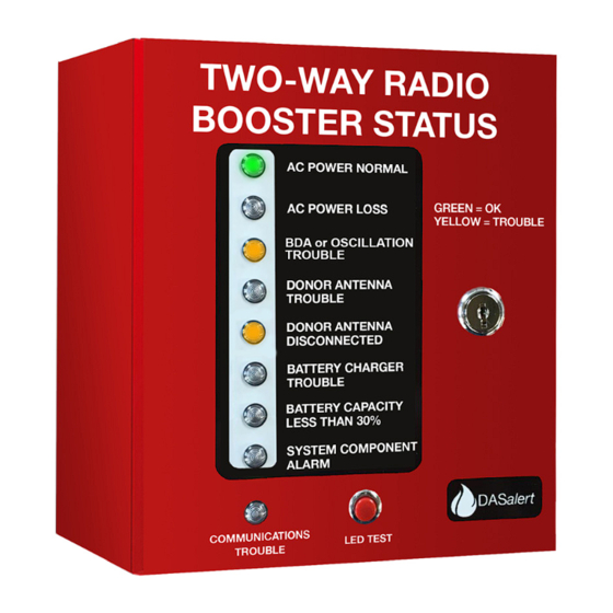
LED Panel Indicators This annunciator panel has 9 LEDs on it that show the status of the equipment in the DAS. The functions are described below: LED Functions DESCRIPTION AC Power Normal (Green when AC power is on to the DAS equipment) -
Page 8: Self-Test
If the DASAlert Panel is located close to the building’s Fire Panel (which has an audible alarm triggered by the DAS alarms) then the DASAlert buzzer can be permanently disabled by setting DIP switch SW-2 (switch 9) to the ON position. If the key is lost, contact Technical Support for alternative ways to silence the buzzer. -
Page 9: Wiring Options
Panel. • The length of the cables from the DAS equipment to the Panel is another variable. If the cables are shorter than 20 feet, then no End-of-Line Resistors (EOLR) are required by code to supervise the connections. - Page 10 Figure 3. Wiring Diagram if cable length is less than 20 feet (set switches 1-8 to ON on DIP Switch SW1) DASalert Model 1221 in Fire Command Center Donor Antenna Disconnected Donor Antenna Disconnected - 7 -...
- Page 11 Figure 4. Wiring Diagram with two CAT 5/6 cables if cable length is greater than 20 feet (set switches 1-8 to OFF on DIP Switch SW1) DASalert Model 1221 in Fire Command Center Donor Antenna Disconnected Donor Antenna Disconnected - 8 -...
- Page 12 Figure 5. Wiring Diagram with one CAT 5/6 cable (set switches 1-8 to OFF on DIP Switch SW1). DC power supply located in Fire Command Center. DASalert Model 1221 in Fire Command Center Donor Antenna Disconnected Donor Antenna Disconnected - 9 -...
- Page 13 Figure 6. Wiring Diagram with one CAT 5/6 cable for installations where there are no ßSystem Components and no Oscillation Indication required. (Set all switches on SW1 to OFF except 7 and 8) DASalert Model 1221 in Fire Command Center Donor Antenna Disconnected...
-
Page 14: Dip Switch Settings
DIP SWITCH SW2 (switches 1-8) are used to set the Alarm Detection mode for the signals from the dry relay contacts in the DAS equipment. If the relay closes (is shorted) when there is an alarm, set the switch OFF. If the alarm relay is normally closed (shorted), but is open when there is an alarm, turn the switch ON. - Page 15 Table 3. Factory Default DIP Switch Settings Table 4. Fire Panel Relays - 12 -...
-
Page 16: Panel Aa Battery Backup
AMAZON. Typically, the best practice is to replace them annually when the rest of the DAS is tested. For the backup batteries to operate, DC primary power must be on first. After that, the battery power will cut in automatically if primary DC power on J10 is lost. -
Page 17: Connections To Building's Fire Panel
Connections to Building’s Fire Panel (See Figure 7) The Fire Panel should be connected to J5, J12, J14 and J16 at the bottom of the panel’s main PC board. The connectors as shown will mate with the panel’s independent internal dry relays to signal alarms to the Fire Panel. -
Page 18: Relay And End-Of-Line Resistor Connections To Fire Panel
Figure 7. Relay and End-of-Line Resistor Connections (ELOR) to Fire Panel Comm Trouble From J5 on Comm Trouble Main PCB. From J5 on ELOR on J6 Main PCB. ELOR on J6 - 15 -... -
Page 19: External Detection Of Donor Antenna Disconnection
Figure 8. Antenna Monitor Connection Diagram External Detection of Donor Antenna Disconnection UL-2524 requires that if the outdoor donor antenna is disconnected an alarm should be triggered. In the event that the BDA in use does not sense this condition to output an alarm relay closure, an external method using a bias-T can be configured as shown in Figure 8. -
Page 20: Specifications
Specifications - 17 -... - Page 21 Specifications ... Continued - 18 -...
Need help?
Do you have a question about the 1221 and is the answer not in the manual?
Questions and answers