Table of Contents
Advertisement
Quick Links
CAUTION, MICROWAVE RADIATION .................................................................................................... 3
WARNING ................................................................................................................................................. 3
SERVICING ............................................................................................................................................. 4
GENERAL INFORMATION ....................................................................................................................... 4
PRODUCT SPECIFICATIONS ................................................................................................................. 5
APPEARANCE VIEW .............................................................................................................................. 6
OPERATION SEQUENCE ........................................................................................................................ 7
FUNCTION OF IMPORTANT COMPONENTS ....................................................................................... 9
TROUBLESHOOTING GUIDE ............................................................................................................... 10
TEST PROCEDURE .............................................................................................................................. 11
TOUCH CONTROL PANEL ASSEMBLY .............................................................................................. 18
COMPONENT REPLACEMENT AND ADJUSTMENT PROCEDURE .................................................. 23
MICROWAVE MEASUREMENT ........................................................................................................... 29
WIRING DIAGRAM ................................................................................................................................ 30
PICTORIAL DIAGRAM .......................................................................................................................... 33
CONTROL PANEL CIRCUIT .................................................................................................................. 34
PRINTED WIRING BOARD .................................................................................................................... 35
PARTS LIST .......................................................................................................................................... 36
SERVICE MANUAL
STR
TURN
KG PCS MICRO
COOK
AUTO
TOP GRIL L
MICRO
BOTTO M GRIL L
10m in.
1mi n.
10s ec.
BREA KFAST
PIZZ A
MIXEED GRILL
OVEN CHIPS
BAKED POTATOE S
MODELS
AUTO
AUTO
COOK
DEFR OST
1 Chilled Ready
Meals
2 Frozen Ready
1 Meat Joint
meals
3 Roast Beef/L
2 Poultry
amb
4 Roast Pork
3 Chicke n Portion
s/
5 Roast Poultry
Steak / Chops
6 Crispy Crumb
4 Minced Meat
Foods
7 Qulche / pie
5 Bread
Kg
Lb g
oz
LESS
MORE
MICR OWAV E
POWE R LEVE L
GRIL L
DUAL
GRIL L
STOP /
STA RT
CLEA R
AUTO MINU TE
TIME R
Kg/ Lb AUTO STAR T
CLOC K
In interests of user-safety the oven should be restored to
its original condition and only parts identical to those
specified should be used.
TABLE OF CONTENTS
SHARP CORPORATION
R-671M - 1
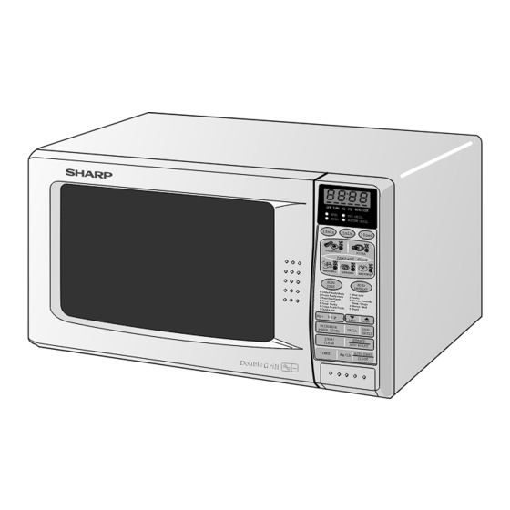
MICROWAVE OVEN WITH
TOP AND BOTTOM GRILLS
R-671(B)M
R-671(W)M
S8805R671M//
Page
Advertisement
Table of Contents

Related Manuals for Sharp R-671(B)M


Summary of Contents for Sharp R-671(B)M
-
Page 1: Table Of Contents
KG PCS MICRO COOK AUTO TOP GRIL L MICRO BOTTO M GRIL L 10m in. 1mi n. 10s ec. BREA KFAST PIZZ A R-671(B)M MIXEED GRILL OVEN CHIPS BAKED POTATOE S MODELS AUTO AUTO COOK DEFR OST 1 Chilled Ready Meals... -
Page 2: Caution, Microwave Radiation
GENERAL IMPORTANT INFORMATION This Manual has been prepared to provide Sharp Corp. Service engineers with Operation and Service Information. It is recommended that service engineers carefully study the entire text of this manual, so they will be qualified to render satisfactory customer service. -
Page 3: Servicing
If the water remains cold carry out 3D checks and re-examine the Sharp recommend that wherever possible fault-finding is connections to the component being tested. carried out with the supply disconnected. It may in, some... -
Page 4: Product Specifications
PRODUCT DESCRIPTION SPECIFICATION ITEM DESCRIPTION Power Requirements 230-240V 50 Hertz Single phase, 3 wire earthed Power Consumption Microwave cooking 1.3 kW Approx. 5.8 A Top Grill mode 0.75 kW Approx. 3.1 A Grill cooking Bottom Grill mode 0.45 kW Approx. 1.9 A Top and Bottom mode 1.15 kW Approx. -
Page 5: Appearance View
APPEARANCE VIEW 1. Control panel 2. Oven lamp 3. Grill heating element (Top Grill) 4. Door opening button 9. Door seals and sealing surfaces 5. Waveguide cover 10.Ventilation openings 6. Oven cavity 11.Outer cabinet 7. Turntable motor shaft 12.Power supply cord 8. -
Page 6: Operation Sequence
OPERATION SEQUENCE 5. When the oven door is opened during a cooking cycle, OFF CONDITION the switches come to the following condition. Closing the door activates the primary latch switch and the stop switch. Switch Contact Condition During Oven Door IMPORTANT: Cooking Open(No cooking) - Page 7 OPERATION SEQUENCE CONT TOP GRILL MODE lamp are de-energized. 6. The relay RY5 stays closed for five (5) minutes, and the In this mode, the food is cooked by the grill heating fan motor operates. element (top grill). Enter the cooking time by pressing the TIME keys and select the TOP GRILL mode by pressing DUAL COOKING CONDITION the GRILL key once.
-
Page 8: Function Of Important Components
OPERATION SEQUENCE CONT 6. The relay RY5 stays closed for five (5) minutes, and the Specified cooking Limited power Time base fan motor operates. Cooking mode time (minutes) output (%) (seconds) Microwave (100%) BREAKFAST COOKING Top Grill PIZZA COOKING Bottom Grill INSTANT COOKING Top Grill and 10 (Top) -
Page 9: Troubleshooting Guide
FUNCTION OF IMPORTANT COMPONENTS CONT DOOR OPEN MECHANISM THERMAL CUT-OUT 150˚C (OVEN) The door can be opened by pushing the open button on the The thermal cut-out protects the oven against over heating control panel. When the button is pushed, the open lever during grill cooking, also the thermal cut-out is designed pushes the lower latch head on the door upward. -
Page 10: Test Procedure
TEST PROCEDURES TEST PROCEDURE A B C D E E E F F G H I J J K K L M N N N N N N O POSSIBLE CAUSE DEFECTIVE PARTS PROBLEM CONDITION Fuse 15A blows when power cord is plugged into wall outlet. - Page 11 TEST PROCEDURES CONT PROCEDURE COMPONENT TEST LETTER MAGNETRON TEST NEVER TOUCH ANY PART IN THE CIRCUIT WITH YOUR HAND OR AN INSULATED TOOL WHILE THE OVEN IS IN OPERATION. CARRY OUT 3D CHECKS. Isolate the magnetron from high voltage circuit by removing all leads connected to filament terminal. To test for an open circuit filament use an ohmmeter to make a continuity test between the magnetron filament terminals, the meter should show a reading of less than 1 ohm.
- Page 12 TEST PROCEDURES CONT PROCEDURE COMPONENT TEST LETTER Initial temperature ....................T1 = 11°C Temperature after (52 + 3) = 55 sec ..............T2 = 21°C Temperature difference Cold-Warm ..............∆T1 = 10C Measured output power The equation is “P = 80 x ∆T” ............P = 80 x 10°C = 800 Watts ±...
- Page 13 TEST PROCEDURES CONT PROCEDURE COMPONENT TEST LETTER HIGH VOLTAGE CAPACITOR TEST CARRY OUT 3D CHECKS. A. Isolate the high voltage capacitor from the circuit. B. Continuity check must be carried out with measuring instrument which is set to the highest resistance range.
- Page 14 TEST PROCEDURES CONT PROCEDURE COMPONENT TEST LETTER BLOWN FUSE F8A CARRY OUT 3D CHECKS If the fuse F8A is blown when the door is opened, check the primary latch switch, monitor switch and monitor resistor. If the fuse F8A is blown by incorrect door switching replace the defective switch(es) and the fuse F8A. CARRY OUT 4R CHECKS.
- Page 15 TEST PROCEDURES CONT PROCEDURE COMPONENT TEST LETTER TOUCH CONTROL PANEL ASSEMBLY TEST The touch control panel consists of circuits including semiconductors such as LSI, ICs, etc. Therefore, unlike conventional microwave ovens, proper maintenance can not be performed with only a voltmeter and ohmmeter.
- Page 16 TEST PROCEDURES CONT PROCEDURE COMPONENT TEST LETTER RELAY TEST CARRY OUT 3D CHECKS. Remove the outer case and check voltage between Pin Nos. 1 and 3 of the 5 pin connector (A) on the control unit with an A.C. voltmeter. The meter should indicate rated voltage, if not check oven circuit.
-
Page 17: Touch Control Panel Assembly
TOUCH CONTROL PANEL ASSEMBLY OUTLINE OF TOUCH CONTROL PANEL The touch control section consists of the following units as 3) Synchronizing Signal Circuit shown in the touch control panel circuit. The power source synchronizing signal is available in order to compose a basic standard time in the clock circuit. - Page 18 DESCRIPTION OF LSI LSI(IZA921DR) The I/O signal of the LSI(IZA921DR) are detailed in the following table. Pin No. Signal Description VL2-VL1 Power source voltage input terminal. Standard voltage for LCD. AN7-AN5 Terminal to change functions according to the Model DC voltage in accordance with the model in operation is applied to set up its function Terminal not used.
- Page 19 DESCRIPTION OF LSI CONT Pin No. Signal Description 20-22 P46-P44 Terminal not used. INT 1 Terminal not used INT0 Signal to synchronized LSI with commercial power source frequency(50Hz). H : GND This is basic timing for time processing of LSI. L (-5V) 20 msec Terminal not used...
- Page 20 DESCRIPTION OF LSI CONT Pin No. Signal Description Signal similar to P17. When any one of G1 line keys on key matrix is touched, a corresponding signal will be input into P14. 45-48 P13-P10 Terminal not used. Cooking mode indicator driving signal To turn on and off the light emitting diode LD8.
- Page 21 TOUCH CONTROL 1. Precautions for Handling Electronic Components For those models, check and repair all the This unit uses CMOS LSI in the integral part of the controls (sensor-related ones included) of the circuits. When handling these parts, the following pre- touch control panel while keeping it connected cautions should be strictly followed.
-
Page 22: Component Replacement And Adjustment Procedure
COMPONENT REPLACEMENT AND ADJUSTMENT PROCEDURE WARNING: Avoid possible exposure to microwave energy. Please follow the instructions below before operating the oven. 1. Disconnect oven from power supply. 1. Door does not close firmly. 2. Make sure that a definite” click” can be heard when the 2. - Page 23 COMPONENT REPLACEMENT AND ADJUSTMENT PROCEDURE CONT move to the right hand side. 9. Remove the magnetron from the waveguide with care so 6. Release the tabs of air intake duct from the oven cavity. the magnetron antenna is not hit by any metal object 7.
- Page 24 10.Now, the turntable motor is free. Slits Re-install 1. Remove the any sharp edges on the turntable motor cover and the base plate with the cutting pliers. Power angle ® POSITIVE LOCK CONNECTOR REMOVAL 1.
- Page 25 COMPONENT REPLACEMENT AND ADJUSTMENT PROCEDURE CONT POWER SUPPLY CORD REPLACEMENT Removal Re-install 1. CARRY OUT 3D CHECKS. 1. Insert the moulding cord stopper of power supply cord 2. Remove the one (1) screw holding the green/yellow into the square hole of the power angle, referring to the wire to the power angle.
- Page 26 COMPONENT REPLACEMENT AND ADJUSTMENT PROCEDURE CONT PRIMARY LATCH SWITCH, STOP SWITCH AND MONITOR SWITCH ADJUSTMENT If the monitor latch switch, stop switch and monitor switch 2. The contacts (COM-NO) of the primary latch switch do not operate properly due to a mis-adjustment, the and stop switch interrupt the circuit before the door can following adjustment should be made.
- Page 27 COMPONENT REPLACEMENT AND ADJUSTMENT PROCEDURE CONT 4. Hold the door panel to the door frame with four (4) Note: The door on a microwave oven is designed to act screws. as an electronic seal preventing the leakage of 5. Catch two (2) pins of door panel on two (2) hole of upper microwave energy from oven cavity during cook and lower oven hinges.
-
Page 28: Microwave Measurement
MICROWAVE MEASUREMENT After any repair, the microwve oven must be PROCEDURE checked for microwave leakage to ensure continued 1. Place the beaker containing the water load safe operation. BS EN 60335-2-25 specifies that the inthe oven cavity at the centre of the maximum permitted leakage with a load of 275ml is turntable. -
Page 29: Wiring Diagram
230-240V 50Hz 230-240V 50Hz BLU/15 BRN/15 BLU/15 BRN/15 G-Y/15 G-Y/15 EARTH EARTH F2: FUSE 15A F2: FUSE 15A 0.22µ/250V 0.22µ/250V 10M/ 0.5W 10M/ 0.5W NOISE SUPPRESSION COIL NOISE SUPPRESSION COIL NOISE NOISE FILTER FILTER 680 k/ 0.5W 680 k/ 0.5W 4700p/ 250V 4700p/ 250V 4700p/ 250V... - Page 30 230-240V 50Hz 230-240V 50Hz BLU/15 BRN/15 BLU/15 BRN/15 G-Y/15 G-Y/15 EARTH EARTH 0.22µ/250V F2: FUSE 15A F2: FUSE 15A 0.22µ/250V 10M/ 0.5W 10M/ 0.5W NOISE SUPPRESSION COIL NOISE SUPPRESSION COIL NOISE NOISE FILTER FILTER 680 k/ 0.5W 680 k/ 0.5W 4700p/ 250V 4700p/ 250V 4700p/ 250V...
- Page 31 230-240V 50Hz 230-240V 50Hz BLU/15 BRN/15 BLU/15 BRN/15 G-Y/15 G-Y/15 EARTH EARTH F2: FUSE 15A F2: FUSE 15A 0.22µ/250V 0.22µ/250V 10M/ 0.5W 10M/ 0.5W NOISE SUPPRESSION COIL NOISE SUPPRESSION COIL NOISE NOISE FILTER FILTER 680 k/ 0.5W 680 k/ 0.5W 4700p/ 250V 4700p/ 250V 4700p/ 250V...
-
Page 32: Pictorial Diagram
POWER SUPPLY CORD GH1: TOP GRILL HEATING ELEMENT N.C. LIVE SW3: MONITOR CONTROL UNIT SWITCH TC2: NEUTRAL THERMAL CUT-OUT(OVEN) SW1: PRIMARY LATCH SWITCH CN-C CN-B OVEN LAMP CN-B F 8 A NOISE FILTER FAN MOTOR CN-A CN-A GH2: BOTTOM HEATING HIGH VOLTAGE COMPONENTS ELEMENT SW2: STOP... -
Page 33: Control Panel Circuit
WIRING DIAGRAMS R-671M - 33... -
Page 34: Printed Wiring Board
WIRING DIAGRAMS WH-C WH-A WH-A WH-C (CN - D) (J7) (J5) (J3) (J2) (J8) VRS1 CN - A Figure S-3. Printed Wiring Board R-671M - 34... -
Page 35: Parts List
PARTS LIST ∆ Note: The parts marked " " may cause undue microwave exposure. / The parts marked "*" are used in voltage more than 250V. / "§" Mark: Spare parts delivery section. ELECTRIC PARTS REF. NO. PART NO. § DESCRIPTION Q'TY CODE... - Page 36 Control panel [R-671(B)M] HPNLCB018URF0 Control panel [R-671(W)M] JBTN-B014URF0 Open button [R-671(B)M] JBTN-W008URF0 Open button [R-671(W)M] MSPRCA045WRE0 Open button spring DUNTKC065URK0 T/C key assembly [R-671(B)M] DUNTKC064URK0 T/C key assembly [R-671(W)M] 3-5-1 FUNTKC062URE0 Key unit [R-671(B)M] 3-5-1 FUNTKC063URE0 Key unit [R-671(W)M] GMADIA018URR0...
- Page 37 Screw: 4mm x 8mm 7- 7 XOTSD40P10000 Screw: 4mm x 10mm 7- 8 XOTSD40P12RV0 Screw: 4mm x 12mm 7- 9 XOTSF40P12000 Screw: 4mm x 12mm R-671(B)M 7- 9 XOTSE40P12000 Screw: 4mm x 12mm R-671(W)M 7-10 LX-CZA030WRE0 TTM cover screw 7-11 XBPWW30P05K00...
- Page 38 EXPLODED DIAGRAMS OVEN PARTS 6-10 7-11 1-13 7-11 4-13 4-21 4-13 GH1-1 4-16 4-10 4-24 4-17 1-14 4-15 4-20 4-11 4-23 4-14 4-19 4-12 4-22 4-26 4-25 4-18 NOTE: In the event of removing the turntable motor cover, this part should be refit- ted using screw connection: LX-CZS030WRE0 (Ref.
- Page 39 EXPLODED DIAGRAMS CONTROL PANEL PARTS 3 - 7 3-1E 3 - 1 3-1F 3-1D 3 - 6 3 - 5 3 - 7 3 - 2 3-5-1 3 - 3 3 - 4 DOOR PARTS R-671M - 39...
- Page 40 Actual wire harness may be different from illustration. TOP PAD ASSEMBLY (FPADBA077URK0) WRAP COVER PRINTED MATTER (SSAKHA047WRE0) RACK DOOR PROTECTION SHEET (SPADPA531WRE0) TURNTABLE TRAY ACCESSORY HOLDER BOTTOM PAD ASSEMBLY (SPADPA010URE0) (FPADBA008URK0) INTO THE OVEN CAVITY PACKING CASE (SPAKCA226URR0); R-671(B)M (SPAKCA227URR0); R-671(W)M Not Replaceable Items. R-671M - 40...
- Page 41 NOTES R-671M - 41...
- Page 42 NOTES R-671M - 42...
- Page 43 'Printed in the U.K. 1998' R-671M - 43...
Need help?
Do you have a question about the R-671(B)M and is the answer not in the manual?
Questions and answers