Sharp R-677W Service Manual

Sharp R-677W Service Manual

Microwave oven with top and bottom grill

Advertisement

Quick Links

CAUTION, MICROWAVE RADIATION .................................................................................................... 2
WARNING ................................................................................................................................................. 3
SERVICING ............................................................................................................................................. 4
PRODUCT SPECIFICATIONS ................................................................................................................. 7
GENERAL INFORMATION ....................................................................................................................... 7
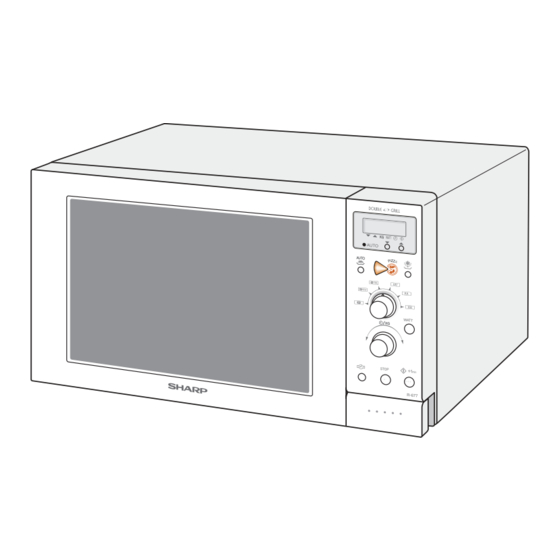
APPEARANCE VIEW .............................................................................................................................. 8
OPERATION SEQUENCE ........................................................................................................................ 9
FUNCTION OF IMPORTANT COMPONENTS ..................................................................................... 11
TROUBLESHOOTING GUIDE ............................................................................................................... 13
TEST PROCEDURE .............................................................................................................................. 14
CONTROL PANEL ASSEMBLY ............................................................................................................ 20
COMPONENT REPLACEMENT AND ADJUSTMENT PROCEDURE .................................................. 24
TEST DATA AT A GLANCE .................................................................................................................. 29
MICROWAVE MEASUREMENT ........................................................................................................... 30
WIRING DIAGRAM ................................................................................................................................ 31
PICTORIAL DIAGRAM .......................................................................................................................... 34
CONTROL PANEL CIRCUIT .................................................................................................................. 35
PRINTED WIRING BOARD .................................................................................................................... 36
PARTS LIST .......................................................................................................................................... 37
CABINET AND UNIT CHASSIS PARTS ................................................................................................. 40
CONTROL PANEL/DOOR PARTS ......................................................................................................... 41
MISCELLANEOUS/PACKING AND ACCESSORIES ............................................................................. 42
SERVICE MANUAL
®
MODELS
R-677(W)
R-677(W)F
R-677(AL)D
In interests of user-safety the oven should be restored to its original
condition and only parts identical to those specified should be used.

TABLE OF CONTENTS

SHARP CORPORATION
R-677 - 1
MICROWAVE OVEN WITH
TOP AND BOTTOM GRILL
R-677(AL)
R-677(W)D
S30331R677EHW
Page

Advertisement

Table of Contents
loading

Summary of Contents for Sharp R-677W

  • Page 1: Table Of Contents

    PICTORIAL DIAGRAM .......................... 34 CONTROL PANEL CIRCUIT ........................35 PRINTED WIRING BOARD ........................36 PARTS LIST ............................37 CABINET AND UNIT CHASSIS PARTS ....................40 CONTROL PANEL/DOOR PARTS ......................41 MISCELLANEOUS/PACKING AND ACCESSORIES ................42 SHARP CORPORATION R-677 - 1...
  • Page 2: Caution Microwave Radiation

    CAUTION CAUTION MICROWAVE RADIATION Personnel should not be exposed to the microwave energy which may radiate from the magnetron or other microwave generating devices if it is improperly used or connected. All input and output microwave connections, waveguides, flanges and gaskets must be secured.
  • Page 3: Warning

    GENERAL IMPORTANT INFORMATION This Manual has been prepared to provide Sharp Corp. Service engineers with Operation and Service Information. It is recommended that service engineers carefully study the entire text of this manual, so they will be qualified to render satisfactory customer service.
  • Page 4: Servicing

    Sharp beveelt ten sterkste aan dat, voor zover mogelijk, defecten worden opgespoord wanneer de stekker uit het Wanneer alle reparaties zijn uitgevoerd en de oven weer in stopcontact is gehaald.
  • Page 5 är kallt utför Du 3 steg kontroller och kontrollerar anslutningarna till varje enskild komponent på nytt. Sharp rekommenderar att felsökning sker med strömmen fränkopplad. Ibland kan det var nödvändigt att koppla på När all service är klar och ugnen ihopskruvad skall ugnens strömmen efter det att höljet avlägsnats, utför da 3 Steg...
  • Page 6 Se l'acqua è rimasta fredda, eseguire i tre controlli iniziali e verificare Sharp raccomanda, nei limiti del possibile, che la ricerca nuovamente i collegamenti del componente in questione. dei guasti avvenga in assenza di alimentazione elettrica.
  • Page 7: Product Specifications

    PRODUCT DESCRIPTION SPECIFICATION ITEM DESCRIPTION Power Requirements 230 Volts 50 Hertz Single phase, 3 wire earthed Power Consumption Microwave cooking 1.34 kW Approx. 6.0 A Top Grill mode ..... 0.75 kW Approx. 3.3 A Grill cooking Bottom Grill mode ....0.45 kW Approx.
  • Page 8: Appearance View

    APPEARANCE VIEW OVEN 1. Control panel 2. Oven lamp 3. Grill heating element (Top Grill) 4. Door opening button 9. Door seals and sealing surfaces 10.Ventilation openings 5. Waveguide cover 6. Oven cavity 11.Outer cabinet 7. Turntable motor shaft 12.Power supply cord 8.
  • Page 9: Operation Sequence

    OPERATION SEQUENCE OFF CONDITION Switch Contact Condition During Oven Door Closing the door activates the primary latch switch and the Cooking Open(No cooking) stop switch. COM-NO Closed Opened Primary latch Switch COM-NC Opened Closed IMPORTANT: Stop switch COM-NO Closed Opened When the oven door is closed, the contacts COM-NC COM-NO Closed...
  • Page 10 OPERATION SEQUENCE CONT 6. The relay RY5 stays closed for five (5) minutes, and the TOP GRILL MODE fan motor operates. In this mode, the food is cooked by the grill heating element (top grill). Select the TOP GRILL mode with the DUAL COOKING CONDITION COOKING MODE selector.
  • Page 11: Function Of Important Components

    OPERATION SEQUENCE CONT PIZZA COOKING Specified cooking Limited power Time base Cooking mode time (minutes) output (%) (seconds) PIZZA automatically works out the correct cooking mode Microwave (100%) and time for cooking. Chose menu with the PIZZA button Top grill and enter the weight of the food with the TIME/WEIGHT Bottom grill dial.
  • Page 12 FUNCTION OF IMPORTANT COMPONENTS CONT SPECIAL FUSE F1 20A down. The thermal cut-out will cut back in at 130˚C. If the wire harness or electrical components are short- circuited, this fuse F1 blows to prevent an electric shock of TURNTABLE MOTOR TTM fire hazard.
  • Page 13: Troubleshooting Guide

    TROUBLESHOOTING GUIDE CONT TEST PROCEDURE A B C D E E E F F G H I J J K K L M N N N N N N O POSSIBLE CAUSE DEFECTIVE PARTS PROBLEM CONDITION Fuse F1 15A blows when power cord is plugged into wall outlet.
  • Page 14: Test Procedure

    TEST PROCEDURES PROCEDURE LETTER COMPONENT TEST MAGNETRON TEST NEVER TOUCH ANY PART IN THE CIRCUIT WITH YOUR HAND OR AN INSULATED TOOL WHILE THE OVEN IS IN OPERATION. CARRY OUT 3D CHECKS. Isolate the magnetron from high voltage circuit by removing all leads connected to filament terminal. To test for an open circuit filament use an ohmmeter to make a continuity test between the magnetron filament terminals, the meter should show a reading of less than 1 ohm.
  • Page 15 TEST PROCEDURES CONT PROCEDURE COMPONENT TEST LETTER ± JUDGMENT: The measured output power should be at least 15 % of the rated output power. CAUTION: 1°C CORRESPONDS TO 80 WATTS. REPEAT MEASUREMENT IF THE POWER IS INSUFFICIENT. 1000g 1000g 1000g T1˚C T2˚C Heat up for 55 sec...
  • Page 16 TEST PROCEDURES CONT PROCEDURE COMPONENT TEST LETTER SWITCH TEST CARRY OUT 3D CHECKS. Isolate the switch to be tested and using an ohmmeter check between the terminals as described in the following table. Table: Terminal Connection of Switch COM; Common terminal, Plunger Operation COM to NO COM to NC...
  • Page 17 TEST PROCEDURES CONT PROCEDURE COMPONENT TEST LETTER NOISE FILTER TEST LINE CROSS CAPACITOR 0.22µ/250V FUSE 15A NOISE CARRY OUT 3D CHECKS. FILTER 10M/0.5W Disconnect the leads from the terminals of noise filter. NOISE SUPPRESSION COIL Using an ohmmeter, check between the terminals as described in the following table.
  • Page 18 TEST PROCEDURES CONT PROCEDURE COMPONENT TEST LETTER TOUCH CONTROL PANEL ASSEMBLY TEST The touch control panel consists of circuits including semiconductors such as LSI, ICs, etc. Therefore, unlike conventional microwave ovens, proper maintenance can not be performed with only a voltmeter and ohmmeter.
  • Page 19 TEST PROCEDURES CONT PROCEDURE COMPONENT TEST LETTER PROCEDURES TO BE TAKEN WHEN THE FOIL PATTERN ON THE PRINTED WIRING BOARD (PWB) IS OPEN To protect the electronic circuits, this model is provided with a fine foil pattern added to the primary on the PWB, this foil pattern acts as a fuse.
  • Page 20: Control Panel Assembly

    CONTROL PANEL ASSEMBLY OUTLINE OF CONTROL PANEL The touch control section consists of the following units as 4) ACL Circuit shown in the touch control panel circuit. A circuit to generate a signals which resets the LSI to the initial state when power is supplied. The principal functions of these units and the signals communicated among them are explained below.
  • Page 21 DESCRIPTION OF LSI CONT LSI(IXA201DR) The I/O signal of the LSI(IXA201DR) are detailed in the following table. Pin No. Signal Description Oven lamp and turntable motor driving signal(Square Waveform : 50Hz). To turn on and off shut-off relay (RY1). 20 msec The square waveform voltage is delivered to the relay (RY1) driving circuit .
  • Page 22 DESCRIPTION OF LSI CONT LSI(IXA201DR) The I/O signal of the LSI(IXA201DR) are detailed in the following table. Pin No. Signal Description RESET Auto clear terminal. Signal is input to reset the LSI to the initial state when power is applied. Temporarily set to "L"...
  • Page 23 SERVICING 1. Precautions for Handling Electronic Components For those models, check and repair all the controls (sensor-related ones included) of the This unit uses CMOS LSI in the integral part of the touch control panel while keeping it connected circuits. When handling these parts, the following pre- cautions should be strictly followed.
  • Page 24: Component Replacement And Adjustment Procedure

    Oven lamp, Magnetron, High voltage transformer To prevent an electric shock, take the following and Oven cavity. manners. 3) Sharp edge: 1. Before wiring, Bottom plate, Oven cavity, Weveguide flange, 1) Disconnect the power supply. Chassis support and other metallic plate.
  • Page 25 10.Now, the turntable motor is free. Slits Re-install 1. Remove the any sharp edges on the turntable motor cover and the base plate with the cutting pliers. Power angle R-677 - 25...
  • Page 26 COMPONENT REPLACEMENT AND ADJUSTMENT PROCEDURE CONT FAN MOTOR REPLACEMENT REMOVAL Because the hole (for shaft) of it may be- come bigger than a standard one. 1. CARRY OUT 3D CHECKS. 5. Now, the fan motor is free. 2. Disconnect the wire leads from the fan motor. 3.
  • Page 27 COMPONENT REPLACEMENT AND ADJUSTMENT PROCEDURE CONT POWER SUPPLY CORD REPLACEMENT Removal Re-install 1. CARRY OUT 3D CHECKS. 1. Insert the moulding cord stopper of power supply cord 2. Remove the one (1) screw holding the green/yellow into the square hole of the power angle, referring to the wire to the power angle.
  • Page 28 COMPONENT REPLACEMENT AND ADJUSTMENT PROCEDURE CONT PRIMARY LATCH SWITCH, STOP SWITCH AND MONITOR SWITCH ADJUSTMENT If the primary latch switch, stop switch and monitor switch results (play of the door) should be less than 0.5mm. do not operate properly due to a mis-adjustment, the 2.
  • Page 29: Test Data At A Glance

    COMPONENT REPLACEMENT AND ADJUSTMENT PROCEDURE CONT 4. Hold the door panel to the door frame with four (4) tight. Therefore, occasional appearance of mois- screws. ture, light or sensing of gentle warm air movement 5. Catch two (2) pins of door panel on two (2) hole of upper around oven door is not abnormal and do not of and lower oven hinges.
  • Page 30: Microwave Measurement

    MICROWAVE MEASUREMENT Recommended instruments are: After adjustment of door latch switches, monitor switch NARDA 8100 and door are completed individually or collectively, the NARDA 8200 following leakage test must be performed with a survey HOLADAY HI 1500 instrument and it must be confirmed that the result meets SIMPSON 380M the requirements of the performance standard for micro- 2.
  • Page 31: Wiring Diagram

    CIRCUIT DIAGRAMS Note: AC CORD CONNECTION SCHEMATIC BRN : BROWN NOTE: CONDITION OF OVEN BLU : BLUE 1. DOOR CLOSED. G-Y : GREEN AND YELLOW STRIPE 2. PLUGGED IN OVEN. /15 : SECTIONAL AREA OF 1.5mm MIN. 3. NOTHING APPEARS ON DISPLAY. "...
  • Page 32 CIRCUIT DIAGRAMS CONT SCHEMATIC NOTE: CONDITION OF OVEN 1. DOOR CLOSED. 2. MICROWAVE COOKING MODE SELECTED. 3. POWER LEVEL CHOSEN. 4. COOKING TIME ENTERED. 5. STRAT BUTTON PRESSED. NOISE F2: FUSE F8A FILTER CONTROL UNIT SW2: STOP SWITCH SW3: SW1: PRIMARY LATCH SWITCH MONITOR SWITCH Figure O-2 Oven Schematic-Microwave cooking Condition SCHEMATIC...
  • Page 33 CIRCUIT DIAGRAMS CONT SCHEMATIC NOTE: CONDITION OF OVEN Indicates components with potential above 250 V. 1. DOOR CLOSED. 2. TOP AND BOTTOM GRILL COOKING MODE SELECTED. 3. COOKING TIME ENTERED. 4. STRAT BUTTON PRESSED. NOISE F2: FUSE F8A FILTER CONTROL UNIT SW2: STOP SWITCH SW3:...
  • Page 34: Pictorial Diagram

    CIRCUIT DIAGRAMS CONT R-677 - 34...
  • Page 35: Control Panel Circuit

    CIRCUIT DIAGRAMS CONT R-677 - 35...
  • Page 36: Printed Wiring Board

    CIRCUIT DIAGRAMS CONT WH-A WH-A CN - D (J7) (J5) (J3) (J2) (J8) MICRO VRS1 CN - A Figure S-3. Printed Wiring Board R-677 - 36...
  • Page 37: Parts List

    PARTS LIST ∆ Note: The parts marked " " may cause undue microwave exposure. / The parts marked "*" are used in voltage more than 250V. / "§" Mark: Spare parts delivery section. ELECTRIC PARTS REF. NO. PART NO. § DESCRIPTION Q'TY CODE...
  • Page 38 PARTS LIST CONT CONTROL PANEL PARTS CONT REF. NO. PART NO. § DESCRIPTION Q'TY CODE VRD-B12EF102J Resistor 1.0k ohm 1/4W VRD-B12EF241J Resistor 240 ohm 1/4W VRD-B12EF472J Resistor 4.7k ohm 1/4W VRD-B12EF153J Resistor 15k ohm 1/4W VRD-B12EF472J Resistor 4.7k ohm 1/4W VRD-B12EF332J Resistor 3.3k ohm...
  • Page 39 PARTS LIST CONT DOOR PARTS 5- 1 DDORFA001URY0 Door panel assembly 5- 2 GWAKPW200URF0 Door frame R-677(W) ∆ 5- 2 GWAKPA200URR0 Door frame R-677(AL) 5- 3 LSTPPA158WRF1 Latch head 5- 4 LSTPPA012URF1 Glass stopper 5- 5 MSPRTA141WRE0 Latch spring 5- 6 PGLSPA028URE0 Front door glass 5- 7...
  • Page 40: Cabinet And Unit Chassis Parts

    CABINET AND UNIT CHASSIS PARTS OVEN PARTS 6-10 4-13 4-21 4-13 4-16 4-28 4-10 4-24 4-17 7-10 4-15 4-20 4-11 4-23 4-14 4-12 4-22 NOTE: In the event of removing the turntable motor cover, this part should be refit- ted using screw connection: LX-CZS030WRE0 (Ref.
  • Page 41: Control Panel/Door Parts

    CONTROL PANEL/DOOR PARTS CONTROL PANEL PARTS 3-1D 3-1E 3-1F 3-12 x 5 3-11 3-12 x 6 3-10 DOOR PARTS R-677 - 41...
  • Page 42: Miscellaneous/Packing And Accessories

    TOP PAD ASSEMBLY (FPADBA010URK0) OVEN BAG PRINTED MATTER (SSAKHA041WRE0) RACK DOOR PROTECTION SHEET (SPADPA026URE0) TURNTABLE TRAY ACCESSORY HOLDER BOTTOM PAD ASSEMBLY (SPADPA014URE0) (FPADBA009URK0) INTO THE OVEN CAVITY PACKING CASE (SPAKCA429URR0); Not Replaceable Items. '2003 SHARP CORP Printed in U.K. R-677 - 42...

This manual is also suitable for:

R-677R-677fR-677wfR-677dR-677aldR-677al ... Show all

Table of Contents