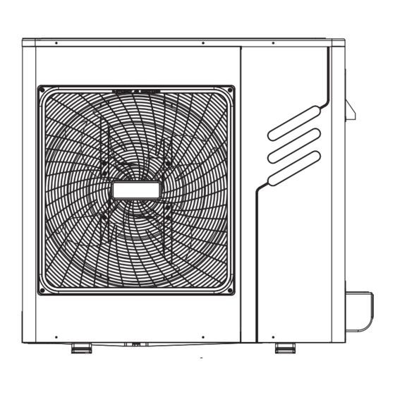
Bosch Climate 5000 VRF MDCI Series Installation Manual
Mini vrf heat pump outdoor unit
Hide thumbs
Also See for Climate 5000 VRF MDCI Series:
- Installation manual (36 pages) ,
- Installation & user manual (24 pages) ,
- Installation and user manual (16 pages)
Advertisement
Quick Links
Mini VRF Heat Pump Outdoor Unit
Climate 5000 VRF
MDCI series, monophase
Installation manual
MDCI8-1
MDCI10-1
MDCI12-1
MDCI14-1
MDCI16-1
Thank you very much for purchasing our air conditioner,
Before using your air conditioner, please read this manual carefully and keep it for future reference.
Advertisement

Summary of Contents for Bosch Climate 5000 VRF MDCI Series
- Page 1 Mini VRF Heat Pump Outdoor Unit Climate 5000 VRF MDCI series, monophase Installation manual MDCI8-1 MDCI10-1 MDCI12-1 MDCI14-1 MDCI16-1 Thank you very much for purchasing our air conditioner, Before using your air conditioner, please read this manual carefully and keep it for future reference.
- Page 2 2 | PRECAUTIONS CONTENTS PAGE WARNING 1. PRECAUTIONS ................2 If the supply cord is damaged, it must be replaced by the 2. ATTACHED FITTINGS ..............3 manufacturer or its service agent or a similarly qualified 3. OUTDOOR UNIT INSTALLATION ..........4 person in order to avoid a hazard.
- Page 3 ATTACHED FITTINGS | 3 An insufficient power supply capacity or inappropriate installation 6) Reamer may cause fire. 7) Gas leak detector Use the specified cables for wiring connect the terminals 8) Tape measure securely fix. To prevent external forces applied to the 9) Thermometer terminals from affecting the terminals.
- Page 4 4 | OUTDOOR UNIT INSTALLATION 3.2 Installation space (Unit:mm) Strong Strong wind wind Fig. 2-2 Installation in the following places may result in some ■ troubles. Do not install the unit in such places below. • A place full of machine oil. •...
- Page 5 INSTALL THE CONNECTING PIPE | 5 Parallel connect the two units or above 3.4 Water Outlet • Four condensed water outlets on the chassis for selection display as the follow figure: >300 Outlet for power and connecting pipes >600 >2000 Reserve water outlet (Need to knock open) Fig.
- Page 6 6 | INSTALL THE CONNECTING PIPE Table 4-1 4.4 Connecting method Select refrigerant pipe ■ Fat pipe Table 4-2 Pipe definition Pipe connect position Code Main pipe The pipe between outdoor unit to the first branch of Undersurface Front out pipe Side out pipe Back out pipe indoor unit.
- Page 7 INSTALL THE CONNECTING PIPE | 7 4.5 Confirmation for the diameters of indoor unit Piping sizes at the branch pipe ■ connecting pipes Table 4-6 Size of main pipe and corresponding branch joint and Refrigerant Indoor Unit ■ branch header Capacity Gas Side (Ø) Liquid Side (Ø)
- Page 8 8 | INSTALL THE CONNECTING PIPE When the outdoor unit connects one indoor unit ■ Table 4-10 MODEL The max height drop(m) The length (kW) The number When When of refrigerant of bends outdoor outdoor unit pipe(m) unit is top is bottom 10.5 less than 10...
- Page 9 INSTALL THE CONNECTING PIPE | 9 4.7 Illustration • Indoor unit branch pipe Inner branch pipes are a~f, the size selection please refers Outdoor Unit((Take Model 160 For Example) to Table 4-6. Note: The max. length of the branch pipe should not longer than 15 m.
- Page 10 10 | INSTALL THE CONNECTING PIPE The second cennect methond • Outdoor unit Pipe length(From the nearest branch pipe equivalent length Maximum pipe equivalent length (From the first line branch pipe) Maximum pipe equivalent length The First Line Branch Pipe Indoor unit Fig.
- Page 11 ELECTRICAL WIRING | 11 5. ELECTRICAL WIRING Outdoor unit X Y E P Q E Power Supply Signal wire between indoor/outdoor unit Indoor unit Indoor unit Indoor unit Branch Box Branch Box Branch Box Power Supply Signal wire between indoor units Please use 3-core shielded wire, and connect the shielded layer to Grounding For 8~16 kw (1-Phase) Fig.
- Page 12 12 | ELECTRICAL WIRING Power (380-415V~ 50Hz 3-Phase) Power (220-240V~ 50Hz 1-Phase) (380-415V~ 60Hz 3-Phase) (220-240V~ 60Hz 1-Phase) (208-230V~ 60Hz 3-Phase) (208-230V~ 60Hz 1-Phase) Switch / Circuit breaker Switch / Circuit breaker Power wiring Power wiring wire distribution box (indoor) (outdoor) in broken line table, users can purchase the Central control montior when necessary.please contract...
- Page 13 ELECTRICAL WIRING | 13 NOTE NOTE The air-conditioners can connect with Central Control The wire diameter and continuous length is under the Monitor (CCM). Before operation, please wiring correctly condition that the voltage vibration is within 2 %. If the and set system address and network address of indoor continuous length is exceed showing value, choose the units.
- Page 14 14 | TEST RUNNING Table 5-3 Calculate the refrigerant thickness SW3 (SW-1) A[kg] ≤ critical thickness Obtain network address automati cally Obtain network address manu ally Revocation indoor unit network add ress Counter measure against over high thickness 1 Installmechanicalventilator to reduce the refrigerant thickness under critical level.
- Page 15 NOTES | 15 Mini VRF Heat Pump Outdoor Unit 6 720 844 632 (2015/11)
- Page 16 Bosch Thermotechnik GmbH Junkersstrasse 20-24 D-73249 Wernau www.bosch-thermotechnology.com...


Need help?
Do you have a question about the Climate 5000 VRF MDCI Series and is the answer not in the manual?
Questions and answers