Table of Contents
Advertisement
Quick Links
NOTE: Read the entire instruction manual before starting the
installation.
This symbol → indicates a change since the last issue.
SAFETY CONSIDERATIONS .....................................................1
INTRODUCTION ..........................................................................1
CODES AND STANDARDS........................................................2
LOCATION....................................................................................4
General ......................................................................................4
Location Relative to Cooling Equipment ................................4
Hazardous Locations.................................................................4
Unconfined Space .....................................................................4
Confined Space .........................................................................5
INSTALLATION ...........................................................................5
Air Ducts...................................................................................5
Filter Arrangement....................................................................6
Leveling Legs (If Required).....................................................7
Gas Piping.................................................................................8
Electrical Connections ..............................................................9
Accessories................................................................................9
Venting ......................................................................................9
START-UP PROCEDURES..........................................................9
General ......................................................................................9
Sequence of Operation............................................................11
Start-Up Procedures ................................................................11
Adjustments.............................................................................13
Check Safety Controls ............................................................18
Checklist..................................................................................18
SAFETY CONSIDERATIONS
Installing and servicing heating equipment can be hazardous due to
gas and electrical components. Only trained and qualified person-
nel should install, repair, or service heating equipment.
Untrained personnel can perform basic maintenance functions
such as cleaning and replacing air filters. All other operations must
be performed by trained service personnel. When working on
heating equipment, observe precautions in the literature, on tags,
and on labels attached to or shipped with unit and other safety
precautions that may apply.
Follow all safety codes. In the United States, follow all safety
codes including the National Fuel Gas Code (NFGC) NFPA
54-1999/ANSI Z223.1-1999 and the Installation Standards, Warm
Air Heating and Air Conditioning Systems (NFPA 90B)
ANSI/NFPA 90B.
In Canada, refer to the CAN/CGA-B149.1- and .2-M95 National
Standard of Canada, Natural Gas and Propane Installation Codes
(NSCNGPIC).
These instructions cover minimum requirements and conform to
existing national standards and safety codes. In some instances,
these instructions exceed certain local codes and ordinances,
especially those that may not have kept up with changing residen-
tial construction practices. We require these instructions as a
minimum for a safe installation.
installation, start-up, and
operating instructions
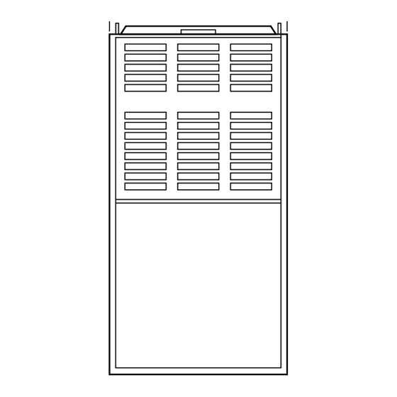
UPFLOW GAS-FIRED
INDUCED-COMBUSTION FURNACES
-1-
Cancels: II 395C-40-13
REGISTERED QUALITY SYSTEM
Wear safety glasses and work gloves. Have a fire extinguisher
available during start-up and adjustment procedures and service
calls.
Recognize safety information. This is the safety-alert symbol
When you see this symbol on the furnace and in instructions or
manuals, be alert to the potential for personal injury.
Understand the signal words DANGER, WARNING, CAUTION,
and NOTE. These words are used with the safety-alert symbol.
DANGER identifies the most serious hazards which will result in
severe personal injury or death. WARNING signifies a hazard
which could result in personal injury or death. CAUTION is used
to identify unsafe practices which would result in minor personal
injury or product and property damage. NOTE is used to highlight
suggestions which will result in enhanced installation, reliability,
or operation
INTRODUCTION
The Model 395CAV, Series H and J Furnaces are available in sizes
44,000 through 154,000 Btuh input capacities.
The design of the upflow gas-fired furnace is C.S.A. (A.G.A. and
C.G.A.) certified for natural and propane gas and for installation
on combustible flooring, in alcoves, attics, basements, closets, or
utility rooms. The furnace is factory-shipped for use with natural
gas. A factory accessory gas conversion kit, as listed on the
furnace rating plate is required to convert furnace for use with
propane gas. The design of this furnace line is not C.S.A. (A.G.A.
and C.G.A.) certified for installation in mobile homes, recreation
vehicles, or outdoors.
CAUTION: Application of this furnace should be in-
doors with special attention given to vent sizing and
material, gas input rate, air temperature rise, and unit
sizing. Improper installation or misapplication of the
furnace can require excessive servicing or cause prema-
ture component failure.
This furnace is designed for a minimum continuous return-air
temperature of 60°F db or an intermittent operation down to 55°F
db such as when used with a night setback thermostat. Return-air
temperature must not exceed a maximum of 85°F db.
395CAV
Series H&J
II 395C-40-15
10-00
EFFICIENCY
RATING
CERTIFIED
CERTIFIED
®
.
Advertisement
Table of Contents


Need help?
Do you have a question about the 395CAV J Series and is the answer not in the manual?
Questions and answers