
Related Manuals for CHROMATEQ DIN-E 512


Summary of Contents for CHROMATEQ DIN-E 512
- Page 1 DIN-E 512/1024/2048 Ethernet to DMX Stand-Alone interface Datasheet & Quickstart Guide ...
- Page 2 Technical Manual & Quick Start Guide Congratulations on your purchase of a CHROMATEQ controller. Please read this manual carefully and thoroughly before using the DIN-E Chromateq. The information presented here provides a useful introduction to the wide range of features, settings and functions available in this compact and versatile DIN-E The DIN-E Technical Manual is written in English and French. (Le manuel technique du DIN-E est rédigé en anglais et en français.) All products and software are developed and designed in France. CHROMATEQ SARL 191 Allée de Lauzard 34980 St Gély du Fesc FRANCE VAT: FR18521458034 Siret: 52145803400027 Web & E-mail: www.chromateq.com Phone: +33 952210755 / +86 13422062209 Whatsapp: +8613422062209 Wechat: Chromateq QQ: 2908265661 Twitter: https://twitter.com/Chromateq ...
-
Page 3: Table Of Contents
Table des matières Introduction Technical device features Software option Connectivity USB drivers installation Multiple USB connections Ethernet connection and configuration DHCP / IP Static DHCP connection Static IP connection Reset of the IP address Connecting to a wifi router Standalone mode settings Device configuration IN/OUT tab "Merge DMX In / DMX Out" option Art-Net/sACN universe range: Clock tab ... - Page 4 Backing up Art-Net or sACN to an external SD card Standalone use Switch to stand-alone mode External and USB power supply Charging the clock battery Play a show via a Micro SD Card How to use IR Remote Previous Remote Control Unit (Before 2022) Functioning for devices without Mode and older devices. Functioning for devices with Modes New Remote Control Unit (2022) Functioning for devices without Mode and older devices. Functioning for devices with Modes Functions descriptions IR Codes IR receiver box NODE mode configurations Setup with the software Network setup NODE Art-Net or sACN mode ...
-
Page 5: Introduction
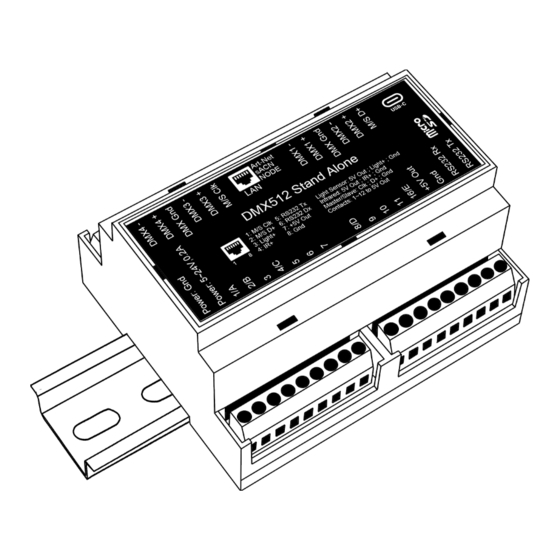
Introduction DIN-E is the ideal DMX standalone device for installation in electrical DIN cabinets with DIN RAILS. The USB to DMX standalone Ethernet DMX device can control from 512 to 2048 channels on 1, 2 or 4 DMX universes. Featuring a robust standalone mode and a wide range of trigger possibilities (RS232, Contacts, Clock, NODE x4 ports, Master/Slave on LAN), this competent device is a smart solution for easy and quick architectural installations and large integration projects. Objectives The purpose of this technical manual is to develop the options managed by the device in standalone mode, for software options, please refer to the software manuals. Technical features Connectors USB-C, Screw terminal (2x9+2x6 pins) Ethernet and RJ45 (External contact x12, Master/Slave, Infrared, Light Sensor, 5S232 in/out) DMX lines Up to 4 x 512 channels 8 and 16-bit DMX channels Internal memory ... -
Page 6: Device Features
device features 4x512 output (Splitter, PC + standalone) or 512 output and DMX 512 512 in input (PC only, DMX recording, DMX IN trigger, DMX merge) 2x512 output, 1024 in output or 512 output and 512 in input DMX 1024 (PC and standalone mode, DMX recording, DMX IN trigger, DMX merge) 4x512 output, 2048 in output or 1024 output and 512 in DMX 2048 input or 1536 output and 512 input (PC and standalone mode, DMX recording, DMX IN trigger, DMX merge) Multiple zones (DMX 1024/2048 5 zones, plays up to 5 scenes simultaneously mode only) Combined areas (DMX 1024/2048 mode only) Clock in real time - RTC Time and calendar triggering ... -
Page 7: Connectivity
Free software updates Connectivity 5- 6 pinsTerminal Block 1- 9 PinsTerminal Block ● ● DMX 4- ● ● DMX 4+ VCC 9-24V ● ● DMX GND TRIG A/1, B/2, 3, C/4, 5, 6, 7 ● DMX 3- 4- 9 PinsTerminal Block ●... -
Page 8: Usb Drivers Installation
USB drivers installation Install USB drivers to communicate with the device and change settings. Installation of USB drivers is required only for Windows at the end of installation. Drivers for Mac and Linux systems are installed automatically. USB drivers verification : In the Windows Device Manager. Check that the device icon is visible in "USB Bus Controllers". If drivers are not installed, the Windows Device Manager lists a device with a yellow warning. On Mac OS, simply check the USB device tree to view "DMX 512 standalone Device". On Linux, use the "lsusb" command to view "DMX 512 standalone Device" as a list. After control software installation and USB drivers Connect the device with the USB cable. ● Start the DEVICETOOL or the software and select "Open USB Device" or "USB" to check the ● success of drivers installation. ... -
Page 9: Ethernet Connection And Configuration
Ethernet connection and configuration Establish Ethernet communication with the device to change its settings in the software options window or via the DEVICETOOL. It can be done in several ways: Live, via an IP Switch or a Wifi router. The device is in DHCP mode by default. Initial steps required Connect the device to the LAN or computer via an RJ45 Ethernet cable. ● ● Power the device via USB cable (5V DC, 0.3A). Connect the computer to the same network (LAN) or device via an RJ45 Ethernet cable. ● DHCP / IP Static In DHCP mode, without responses from a DHCP server after a short time, the device will use static IP mode with its default IP address and wait for the next DHCP request to use DHCP mode. It will therefore always be possible to connect directly to the computer in static IP MODE.The device is in DHCP mode by default. DHCP connection ... -
Page 10: Reset Of The Ip Address
Static IP mode, allows you to communicate directly with an device without necessarily going through another device such as IP switch or router or access point. It is also used on LANs without DHCP server. Static IP mode also allows you to freeze a network configuration and provides better stability to installations designed with multiple devices thanks to an IP switch or routers. The default static values of the device are: IP address: 192.168.0.5 Subnet mask: 255.255.255.0 Setting up the Static IP connection After the required initial steps are completed. ● ● If the device is in Static IP mode. Set the IP address of the computer to an identical IP address range of type ● 192.168.0.x.With "x" different than 5 to avoid identical IP conflicts on the network. Also set the subnet mask to 255.255.255.0. ● Start the software or application. ● ... -
Page 11: Standalone Mode Settings
Implementation of the WIFI network: Set up the WiFi router as a Hotspot to create a new access point. ● ● Or configure the WiFi router as “Bridge” or repeater to join an existing network. It is possible to configure the router in Static IP or DHCP. ● In DHP (default mode of a router) IP addresses are dynamically assigned on the network by ● the DHCP server. After configuring the router, connect the RJ45 ports and configure the device in DHCP or ● static IP mode. Once the device is connected to the router, it can be used and visible on the network. ● Standalone mode settings In standalone mode of the control software, configure the device according to the available options then select and configure the triggers of scenes to be written in memory. ... -
Page 12: Merge Dmx In / Dmx Out" Option
Available configurations will be displayed depending on the connected device depending on whether it has 1.2 or 4 DMX lines. A OUT - Assigns 1 output universe on the DMX line(s), for devices that have more than 1 ● DMX lines duplicate the universe on each. AB OUT - Assigns 1 different output universe on 2 DMX lines, for devices that have 4 DMX ● lines duplicates the first 2 lines on the next 2 lines. A OUT/B or D IN - Assigns 1 output universe on the first line(s) and uses the last DMX line ● as DMX input. ABC OUT - Assigns 1 different universe output on the first 3 DMX lines. ● ABCD OUT - Assigns 1 different universe output on 4 DMX lines. ● AB OUT / D IN - Assigns 1 different output universe on the first 2 lines and uses the last ● DMX line as DMX input. ● ABC OUT / D IN - Assigns 1 different output universe on the first 3 lines and uses the last DMX line as DMX input. "Merge DMX In / DMX Out" option ... -
Page 13: Art-Net/Sacn Universe Range
Optimize the size of shows saved in memory by reducing the number of circuits per universe depending on the channels used. Example: If 150 channels are used in the show, select only the nearest higher value, here 192. Art-Net/sACN universe range: Define the starting universe and the finish universe to write in memory on an external SD card for an Art-Net/sACN show. Cf. "Saving Art-Net or sACN to an external SD card" Clock tab Set up the selected device's internal clock. 1-Update the time in real time 2-Update the time after changing the hours/minutes/second fields. 3-Calibrate the compensation time according to the observed deviation. 4-Update the date. 5-Sync the date and time of the device with that of the computer. 6-Check to take into account the change of summer/winter time 7-Select the days of change of summer/winter time ... -
Page 14: Master/Slave Tab
For devices with an LED display, turn it off after 4 seconds of inactivity by checking the option. Select a default scene to play automatically after the device is turned on (with USB or external power supply). For multi-zones devices it is possible to set a default scene for each area. Note: The selected default start scene loses its priority if another scene uses the "Restore if power off" option. Cf. "Advanced trigger options" Configure the "Select Dimmer channels" option to select separately the Dimmer or RGBW light intensity channels that will be controlled directly by Dimmer mode, dry contacts or via the infrared remote control. Master/Slave tab Connect multiple devices into USB so that they are detected by the software. Use the Master/Slave option to synchronise their standalone mode and DMX universe. When a device is set as a master in the software, the other devices are automatically put in slave mode.There are four different modes of master/slave interaction: By default, desynchronized, LTP, ... -
Page 15: Master/Slave Mode "By Default
and no release. Master/Slave mode "by default" A single device is defined as master (lower serial number by default), the others are automatically defined as slaves.The master device plays the current scene and synchronises the slave devices. The master forces slave devices to play the same scene and the same stage step simultaneously. Slave devices are forced to track the timings and triggers of the master and they cannot act otherwise, play or trigger a scene independently. The master can trigger and stop scenes from slave devices. "Desynchronized" Master/Slave mode One device is defined as master, the others are automatically defined as slaves. All master device triggers are transmitted to slaves. However, slave devices are not synchronised with the master device synchronisation signal and retain individual control. Therefore, slaves can trigger and play different scenes at any time and not synchronised perfectly with those of the master.The master acts as a general remote control imposing the trigger on slaves with total priority.The master can trigger ON and OFF scenes from the slave device. Master/Slave mode "LTP" LTP means "Latest Takes Priority / The latter has Priority".All devices are defined as slaves.The devices are not synchronised with timing and can trigger and play different scenes by themselves.However, device triggers are automatically transmitted to other connected devices and ... -
Page 16: Commands Tab
Commands tab Assign external contacts, among those available for your device, to trigger some standalone mode commands: Dimmer +, Dimmer -, Blackout, Speed +, Speed -, Pause, Scene +, Scene - and Zone. Note: Be careful not to use the same command trigger as the one used for a scene and vice versa. Cf. "Choice of triggers by external contacts" The last assigned contact will take priority over the other. Use 2 types of Short/Hold contact and thus assign an identical contact to 2 different commands. (here as an example with the Dimmer +; Dimmer -) Zones tab The multi-zone option allows you to play multiple scenes simultaneously in defined areas. The tab displays the DMX configuration summary of the associated DMX zones and addresses. ... -
Page 17: Scenes Selection And Configuration
Double-click to switch to edit mode. Set the area settings manually, moving the centrer bar or digitally choosing the range of the area in the fields. Note: Verify that the addresses of DMX patches and devices match the defined areas. Scenes selection and configuration Check to select the scenes to write in memory and assign triggers from those available by your device. Choice of triggers In the "Triggers" tab, select and assign different types of triggers. ... -
Page 18: Infrared Trigger
Infrared Trigger For devices that do not have this trigger option an Infrared kit is available containing an IR receiver and a remote control. Cf. "use of the remote control by infrared" Select a scene from the list and assign it a remote control button from the 15 available buttons. Automatically assign buttons to all scenes in the list by clicking the Infrared icon on the scene list toolbar. ... -
Page 19: Rs232 Trigger
RS232 trigger Use RS232 as a receiver to control the device via another device with the commands also described in the Software Help topic. ... -
Page 20: External Contacts Trigger
External contacts Trigger: Depending on the device, several external contacts are available: Trig A, Trig B, Trig C ..., and the Use a multiplexing device to extend the number of contacts when possible.(from 3 to 7; from 4 to 15; from 5 to 31 ...) Contact reaction time, 5ms (0.005s) Example of multiplexing system with 4 external contacts extended to 15. Select a scene from the list and assign it a contact from those available through the device. Option of triggers Select a trigger option from the drop-down menu next to it. On: Activating the contact makes the scene play (the only trigger action is to start the scene). On/Off: Activating the contact starts the scene, subsequent activation stops the scene.Each trigger action will reverse the stage state (start/stop). Auto Release: The scene is played only while the contact is enabled.When the contact is released, ... -
Page 21: Triggers By Dmx-In
If nothing plays: Play the selected scene if nothing plays. These two interdependent options allow the same contact to be assigned to two different scenes. Note: Be careful not to use the same scene trigger as the one used for a command and vice versa. Cf. "Order tab" The last assigned contact will take precedence over the other. Automatically assign external contacts to all scenes in the list by clicking the external contact icon on the scene list toolbar. Triggers by DMX-IN 255 trigger channels and up to 255 levels per channel are available. Select a scene from the list and assign it a channel number associated with a trigger level.A trigger level corresponds to the threshold above which the scene is triggered. Note: To configure triggers in DMX-IN, one of the DMX lines must be Select as input in the "IN/OUT Config tab." ... -
Page 22: Advanced Trigger Options
The Wi-Light 2 app uses an open protocol for developers with standard communication based on simple UDP commands. Third-party software can establish UDP communication with the software/device and control it using predefined JSON commands.Option only available with devices with an Ethernet port. (see "Communication Development Kit User Manual") Advanced trigger options. Restore after power off By checking this option in the "Triggers" tab, the selected scene takes priority on the boot scene (see "Options tab") when the power supply is restored. If all scenes have the option checked, the last active scene is replayed. Play in priority By checking this option in the "Triggers" tab, the selected scene plays continuously until its end, without taking into account other triggers, except for time triggers and physical buttons on the device. Time triggers ... -
Page 23: Permanent Trigger
Check "Enable trigger" and "disable trigger" to determine a period. Select a date (timetable icon) and time (hour/minutes fields) of trigger activation and then disable trigger. Without shutdown, the scene will play indefinitely until another event replaces it with another scene triggering or manual shutdown. Permanent trigger For example above: the scene plays from Monday to Thursday from 11am to noon from 1st to 20 of each month, from September to April. Check "Repeat every year" to set the monthly and then daily triggers. Select or deselect the months of active triggers in the left wheel. (selection in orange) After selecting the green square for the start day or the red square for the end day, determine the period of the month during which the trigger will be active. Select or deselect the days of the week or the trigger will be active in the right wheel. (selection in orange) Select a start time and an end time of trigger. ... -
Page 24: Priority Of Hourly Trigger
Cf. "Use the remote control" Check "brightness" to activate or disable the trigger according to the ambient light. Once checked this option cancels and replaces the time trigger. Click on the icon to determine if the trigger activates or disables during the upward phase (day to night) or downward phase (night to day). Click the arrow to set a value that corresponds to the light sensitivity and at which the trigger activates or disables. Using the arrows, adjust the value that fits into the dedicated field. Priority of hourly trigger When multiple scenes have the same time trigger (date + hour + minute), only the last scene in the list will be triggered. The others will be ignored when triggering. ... -
Page 25: Save In Memory Option
Save in memory option Check scenes that need to be saved in memory. Click on the "Write in Memory" button Select the desired option in the Scenes Write window. Basic backup Write standalone configuration: Change only certain settings in the configuration of a show ... -
Page 26: Save To An Internal And External Micro Sd Card
already written in memory. Reduces backup time. Write to Memory: Default backup in the internal memory of the device. Save to an internal and external micro SD card For devices with a micro SD port. Save scenes to a micro SD card (Class 10) installed in the device's SD card reader or in the computer drive.The card must be CLASS 10, formatted in FAT or FAT 32 with a maximum capacity of 256 GB.It is recommended to use the largest allocation unit size available when formatting. Write to the SD card of the device: SD card installed in the device drive Write to an external SD card: SD card connected to the computer Note: Save to the root directory of the SD card. Backing up Art-Net or sACN to an external SD card For devices with a micro SD port and an Ethernet port. Art-Net - Write to an external SD card: Save up to 8 universes only on micro SD to render an Art- Net or sACN show independently. Set the universe range in the IN/OUT config tab. ... -
Page 27: Standalone Use
Standalone use Switch to stand-alone mode The device switches to standalone mode automatically after 5 seconds after power on and if no software connection is made. External and USB power supply The external power supply is only used for "Autonomous" mode.But it is possible to connect a USB cable and power supply at the same time, even if this configuration is not recommended.If a USB cable is connected to the device when running in standalone mode, the device will detect a possible connection to a computer but this will not affect the scenes that play. Charging the clock battery Before installing the device in standalone mode, connect it for 1 hour to charge the clock battery and avoid losing the saved time configurations. Play a show via a Micro SD Card To play the SD show standalone, insert the card into the micro SD drive of the device. When powered, the screen displays "Sd" to indicate that the SD file of the project is being played. Note: The show file must be saved to the root directory of the micro SD.It will not be read if the file ... -
Page 28: How To Use Ir Remote
How to use IR Remote Infrared Remote triggers work in standalone and in Live mode when “Get standalone Triggers” is checked in software option window, at the bottom of "Device" section. Previous Remote Control Unit (Before 2022) Functioning for devices without Mode and older devices. Scene trigger buttons (1 to 10) assigned via the software. Scene selector, next or previous. Speed value, increase & decrease Dimmer value, increase & decrease Blackout: Stops the current scene and plays the scene 00. All DMX levels are set to zero. Pause: Freezes the current scene in its state Functioning for devices with Modes Scene trigger buttons (1 to 10) assigned via the software Increase or decrease the value of the selected mode: Scene +/-, Dimmer +/-, Speed +/-, Color +/-. Color mode ... -
Page 29: New Remote Control Unit (2022)
New Remote Control Unit (2022) Functioning for devices without Mode and older devices. Scene trigger buttons (1 to 10) assigned via the software. Scene selector, next or previous. Speed value decrease Speed value increase Dimmer value decrease Dimmer value increase Blackout: Stops the current scene and plays the scene 00. All DMX levels are set to zero. Pause: Freezes the current scene in its state Functioning for devices with Modes Scene trigger buttons (1 to 15) assigned via the software Trigger 1 to 15 with 1 Zone. Trigger 1 to 9 with several Zone. 5 Control Zones available: A, B, C, D, E and Global Zone: [ ] to trigger each Zone in the same time. Increase or decrease the value of the selected mode: ... -
Page 30: Functions Descriptions
Functions descriptions Scene +/-: Each push selects the next or previous scene of the current Zone. Scene are play immediately. Master Dimmer: Increases or decreases the RGB, CMY and dimmer channels of the current zone. The CMY, RGB, Dimmer channels are defined in the Profile of the fixture and the stand-alone mode. Scene Speed: Increases or decreases the speed of the current scene in the current zone. A different speed can be chosen separately for each scene. Zones: Choose a Zone (A,B,C,D,E or Global [ ]). Then select a scene or mode to trig in the selected zone. Modes: Select a Mode from Speed, Dimmer, Colour or Scenes, then use +/- to change values. IR Codes ... -
Page 31: Ir Receiver Box
IR receiver box To use the optional IR remote control, an external circuit with an IR receiver must be connected via an RJ45 port or via the standalone device terminal block. IR PCB pinout -With RJ45 cable, use pins: #8 = Ground; #4 = IR data; #7 = 5V. -With connectors, use pins: O = IR data; V = 5V; G = Ground. Maximum distance from cable to receiver is approx. 20 m. Light sensor The light sensor integrated in the IR box circuit only works with hourly triggers. The external card must be connected via the RJ45 port or via the terminal block. Light sensitivity must be set in the software. See "Time-controlled scenes". ... -
Page 32: Node Mode Configurations
NODE mode configurations Setup with the software Network setup Access the device options window: In the "Ethernet" tab, check "DHCP" to put the device in DHCP mode and apply. To put the device in static IP mode, uncheck "DHCP" and enter the IP address, subnet mask, gateway, and name, and then apply. Cf: "Ether Ethernet connection and configuration" NODE Art-Net or sACN mode The device's Node mode makes it possible to convert Art-Net and sACN signals to DMX. In the Node part, select Node Art-Net to change the settings you want. Configure names with "Short Name" and "Long Name". Change the DMX ports or outputs of the Node by changing the "SubNet" and "DMX Universe", and then apply. Select Node sACN to choose DMX and applied Universes. ... -
Page 33: Setup With The Devicetool
Setup with the DeviceTool Network setup Open the device via USB or Ethernet with the option "Open USB Device" or Open "Ethernet Device. Select the "Network" tab. In the "Ethernet" tab, check "DHCP" to put the device in "DHCP" mode and apply. To put the device in static IP mode, uncheck DHCP and enter the IP address, subnet mask, gateway, and name, then apply. NODE Art-Net or sACN mode The device's Node mode makes it possible to convert Art-Net and sACN signals to DMX. Open the device via USB or Ethernet with the option "Open USB Device" or Open "Ethernet Device. Select the "Fashion" tab. Select Node Art-Net to change the desired settings. Configure names with "Short Name" and "Long Name". Change the DMX ports or outputs of the Node by changing the "SubNet" and "DMX Universe", and then apply. -
Page 34: Configuration With A Web Browser
To use the device in the selected mode, you must restart the device after configuration by unplugging it from the power supply. Switch between Art-Net and sACN mode with long support (5s.) on the Device Mode button and following the network configuration of the device. Configuration with a Web Browser This feature is not currently available. Udp, Broadcast, Unicast, Multicast Art-Net and sACN are communication protocols based on the UDP/IP standard. These 2 protocols integrate DMX frames into Ethernet frames allowing simpler and more convenient wiring with the use of IP switches or WIFI terminals. Several DMX lines can be encapsulated in an Ethernet frame and therefore reduce wiring to 1 single Ethernet line for X DMX lines. Art-Net network data is transmitted in Broadcast or Unicast. Unicast is preferable when using multiple devices on the network and when managing more than 10 DMX universes. ... -
Page 35: Node Wiring Diagram
NODE wiring diagram Reset default device To restore the default values and reset your device, reconfigure the device via USB or Ethernet with the software or DEVICETOOL or app and restart it to take into account the new mode and settings. Change mode directly on the device with a 5 second long press on the mode button. Network NODEs detection Connect multiple devices into the same network to multiply the output DMX universes. Check previous steps Assigning IP addresses and subnet masks. ● Configuring devices via the software or DeviceTool. ● Connecting devices to the network. ● Powering devices. ● If the steps have been followed, the devices are visible on the network by the software or by other ... - Page 36 ...
-
Page 37: Dimensions
Dimensions Dimensions in mm. ... -
Page 38: Wiring Diagram
Wiring Diagram General wiring diagram Standalone Art-Net wiring diagram Master/Slave Standalone wiring diagram ... -
Page 39: Troubleshooting
Troubleshooting The device is not detected by the DeviceTool or Unplug to restart the device. USB software. Change the USB cable Unplug to restart the device. The device is not detected by the DeviceTool or Change the Ethernet cable Ethernet software. Check the selection of the Ethernet network before opening. Check the mode of communication with LED signals and reconfigure the device via USB if necessary Verify that the IP addresses and subnet mask are configured correctly. Update the firmware of the device via the software or DeviceTool The device is not detected on the network. - Page 40 Device without display Select ArtNet, sACN mode again via the software or DeviceTool. If you experience unlisted issues, contact your seller or manufacturer directly to indicate your problem and receive a solution. Product design and specifications are subject to change without prior notice. Older devices (sold before 2020) are not compatible with PRO DMX version 2 Wechat: Chromateq WhatsApp: +8613422062209 QQ: 2908265661 191 Allée de Lauzard Guaranteed products: 1-3-5 years 34980 St Gély du Fesc, FRANCE Software pack: https://chromateq.com/dmx-software- Web: www.chromateq.com downloads/ ...
Need help?
Do you have a question about the DIN-E 512 and is the answer not in the manual?
Questions and answers