Table of Contents
Advertisement
Quick Links
Advertisement
Table of Contents

Related Manuals for CHROMATEQ PRONET-E


Summary of Contents for CHROMATEQ PRONET-E
- Page 1 PRONET-E Ethernet to DMX Stand-Alone interface Datasheet & Quickstart Guide 0...
- Page 2 Technical Manual & Quick Start Guide Congratulations on your purchase of a CHROMATEQ controller. Please read this manual carefully and thoroughly before using the PRONET-E Chromateq. The information presented here provides a useful introduction to the wide range of features, settings and functions available in this compact and versatile PRONET-E The PRONET-E Technical Manual is written in English and French. (Le manuel technique du PRONET-E est rédigé en anglais et en français.) All products and software are developed and designed in France. CHROMATEQ SARL 191 Allée de Lauzard 34980 St Gély du Fesc FRANCE VAT: FR18521458034 Siret: 52145803400027 Web & E-mail: www.chromateq.com Phone: +33 952210755 / +86 13422062209 Whatsapp: +8613422062209 Wechat: Chromateq QQ: 2908265661 Twitter: https://twitter.com/Chromateq ...
-
Page 3: Table Of Contents
Table des matières Introduction Technical specifications Device Features Software options Housing connectivity Front Panel Rear Panel USB drivers installation Multiple USB connections Ethernet connection and configuration DHCP / IP Static DHCP connection Static IP connection Reset of the IP address Connecting to a wifi router Standalone mode settings Device configuration IN/OUT tab "Merge DMX In / DMX Out" option ... - Page 4 Functioning for Interfaces with Modes Functions descriptions IR Codes NODE mode setup Setup with the software Network setup NODE Art-Net or sACN mode Setup with the DeviceTool Network setup NODE Art-Net or sACN mode Setup with a Web Browser UDP, Broadcast, Unicast, Multicast Reset the default device NODE wiring diagram Detecting NODEs on the network Art-Net wiring diagram Housing dimensions Bookmark missing Front panel Bookmark missing ...
-
Page 5: Introduction
Introduction PRONET-E is designed for demanding projects requiring a large number of DMX/Art-Net channels. The software offer up to 24-hour Audio and Video Timeline synchronisation, Midi Time Code, PC Clock triggers, and Live Timeline Record (on the fly). Objectives The purpose of this technical manual is to develop the options managed by the interface in standalone mode, refer to software manuals. Technical specifications Input USB-C and RJ45 Ethernet (10Mb/s) DMX outputs 2x512 or 1024 on 3-pin XLR (XLR 5 optional) DMX mode 2x512, 1024 or 512 In/Out (PC + standalone) Internal memory capacity 100 ~ 1024 steps 32-bit processor ... -
Page 6: Software Options
Supported modes UDP, Broadcast, Unicast, Multicast, fixed IP, DHCP Infrared receiver Infrared remote control (available as an option) 10 scene selections, speed, intensity Main dimension and Infrared options next scene Ethernet protocol (UDP) with a list of possible commands Communication UDP for CLUB-E Compatibility 8 and 16-bit DMX devices RDM (Remote Device Management, bi-directional DMX Yes, with Pro DMX 2 only communication) Wi-Light 2 WEB control with Wi-Light 2 ... -
Page 7: Housing Connectivity
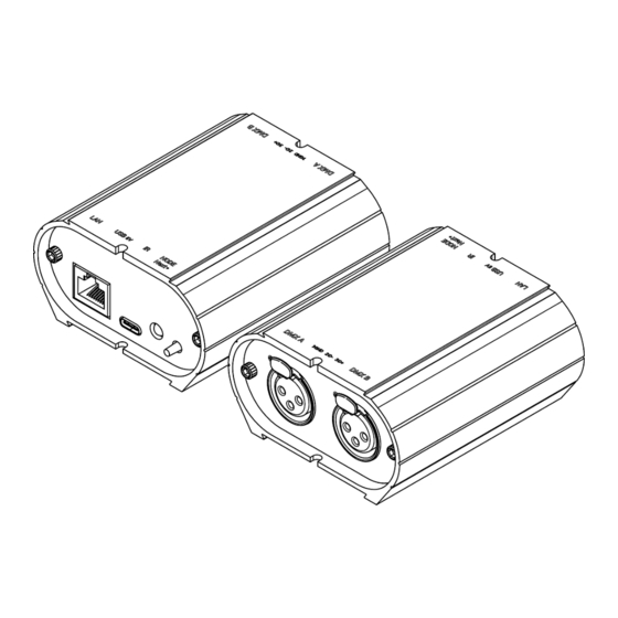
Housing connectivity Front Panel 1 - Output DMX A, 2 - Input / Output DMX B XLR Connector 3 pins 1: Ground 2: Data - 3: Data + Rear Panel 1 - RJ45, Network (LAN) connection 2 - USB-C, power connector (5V. DC, 0.3A) 3 - Infra-red receiver LED, optional 4 - Modes selector (5 s.) Art-Net or sACN 5 - LEDs signals : green (G) et Yellow (Y) ... -
Page 8: Usb Drivers Installation
USB drivers installation Install USB drivers to communicate with the device and change settings. Installation of USB drivers is required only for Windows at the end of installation. Drivers for Mac and Linux systems are installed automatically. USB drivers verification : In the Windows Device Manager. Check that the device icon is visible in "USB Bus Controllers". If drivers are not installed, the Windows Device Manager lists a device with a yellow warning. On Mac OS, simply check the USB device tree to view "DMX 512 Stand Alone Device". On Linux, use the "lsusb" command to view "DMX 512 Stand Alone Device" as a list. After control software installation and USB drivers Connect the device with the USB cable. ● Start the DEVICETOOL and select "Open USB Device" to change the settings. ● Start the software and menu "Tools", then "Options" to change the settings in the "Device" ● page. -
Page 9: Ethernet Connection And Configuration
Ethernet connection and configuration Establish Ethernet communication with the device to change its settings in the software options window or via the DEVICETOOL. It can be done in several ways: Live, via an IP Switch or a Wifi router. The device is in DHCP mode by default. Initial steps required Connect the device to the LAN or computer via an RJ45 Ethernet cable. ● ● Power the device via USB cable (5V DC, 0.3A). Connect the computer to the same network (LAN) or interface via an RJ45 Ethernet cable. ● DHCP / IP Static In DHCP mode, without responses from a DHCP server after a short time, the interface will use static IP mode with its default IP address and wait for the next DHCP request to use DHCP mode. It will therefore always be possible to connect directly to the computer in static IP MODE.The device is in DHCP mode by default. DHCP connection ... -
Page 10: Static Ip Connection
Static IP connection Static IP mode, allows you to communicate directly with an interface without necessarily going through another device such as IP switch or router or access point. It is also used on LANs without DHCP server. Static IP mode also allows you to freeze a network configuration and provides better stability to installations designed with multiple devices thanks to an IP switch or routers. The default static values of the device are: IP address: 192.168.0.5 Subnet mask: 255.255.255.0 Setting up the Static IP connection ● After the required initial steps are completed. If the device is in Static IP mode. ● Set the IP address of the computer to an identical IP address range of type ● 192.168.0.x.With "x" different than 5 to avoid identical IP conflicts on the network. Also set the subnet mask to 255.255.255.0. ● Start the software or application. ●... -
Page 11: Standalone Mode Settings
Implementation of the WIFI network: Set up the WiFi router as a Hotspot to create a new access point. ● ● Or configure the WiFi router as “Bridge” or repeater to join an existing network. It is possible to configure the router in Static IP or DHCP. ● In DHP (default mode of a router) IP addresses are dynamically assigned on the network by ● the DHCP server. After configuring the router, connect the RJ45 ports and configure the device in DHCP or ● static IP mode. Once the device is connected to the router, it can be used and visible on the network. ● Standalone mode settings In standalone mode of the control software, configure the device according to the available options then select and configure the triggers of scenes to be written in memory. ... -
Page 12: Merge Dmx In / Dmx Out" Option
Available configurations will be displayed depending on the connected device depending on whether it has 1.2 or 4 DMX lines. A OUT - Assigns 1 output universe on the DMX line(s), for devices that have more than 1 ● DMX lines duplicate the universe on each. ● AB OUT - Assigns 1 different output universe on 2 DMX lines, for devices that have 4 DMX lines duplicates the first 2 lines on the next 2 lines. A OUT/B or D IN - Assigns 1 output universe on the first line(s) and uses the last DMX line ● as DMX input. ABC OUT - Assigns 1 different universe output on the first 3 DMX lines. ● ● ABCD OUT - Assigns 1 different universe output on 4 DMX lines. AB OUT / D IN - Assigns 1 different output universe on the first 2 lines and uses the last ● DMX line as DMX input. ABC OUT / D IN - Assigns 1 different output universe on the first 3 lines and uses the last ● DMX line as DMX input. "Merge DMX In / DMX Out" option ... -
Page 13: Art-Net/Sacn Universe Range
Assign any universe of the software to any DMX line assigned to output, choosing line by line (U1, U2...). Optimize the size of shows saved in memory by reducing the number of circuits per universe depending on the channels used. Example: If 150 channels are used in the show, select only the nearest higher value, here 192. Art-Net/sACN universe range: Define the starting universe and the finish universe to write in memory on an external SD card for an Art-Net/sACN show. Cf: "Saving Art-Net or sACN to an external SD card" Options tab For devices with an LED display, turn it off after 4 seconds of inactivity by checking the option. Select a default scene to play automatically after the interface is turned on (with USB or external power supply). For multi-zones devices it is possible to set a default scene for each area. ... -
Page 14: Scenes Selection And Configuration
Note: The selected default start scene loses its priority if another scene uses the "Restore if power off" option. Cf: "Advanced trigger options" Configure the "Select Dimmer channels" option to select separately the Dimmer or RGBW light intensity channels that will be controlled directly by Dimmer mode, dry contacts or via the infrared remote control. Scenes selection and configuration Check to select the scenes to write in memory and assign triggers from those available by your device. ... -
Page 15: Triggers Selection
Triggers selection In the "Triggers" tab, select and assign different types of triggers. Infrared Trigger For devices that do not have this trigger option an Infrared kit is available containing an IR receiver and a remote control. Cf: "use of the remote control by infrared" Select a scene from the list and assign it a remote control button from the 15 available buttons. Automatically assign buttons to all scenes in the list by clicking the Infrared icon on the scene list toolbar. Triggers via Wi-light 2 app and UDP commands When connected to a local network with a WIFI access point, it is possible to trigger and control the interface with the Wi-Light 2 app for Android and iOS when it runs in standalone mode.This ... -
Page 16: Advanced Trigger Options
local mode is also available on the internet with the Web Remote option. Each device, interface and mobile, must be connected to the same access point in DHCP (recommended) or fixed IP mode.The application will then detect the interface and display the list of scenes and other possible controls and commands. The Web Remote control option requires you to create a user account and save your interfaces locally first. Please refer to the Wi-Light 2 manual to use this mode. The Wi-Light 2 app uses an open protocol for developers with standard communication based on simple UDP commands. Third-party software can establish UDP communication with the software/interface and control it using predefined JSON commands.Option only available with interfaces with an Ethernet port.(see "Communication Development Kit User Manual") Advanced trigger options. Restore after power off By checking this option in the "Triggers" tab, the selected scene takes priority on the boot scene (see "Options tab") when the power supply is restored. If all scenes have the option checked, the last active scene is replayed. -
Page 17: Save In Memory Option
Save in memory option Check scenes that need to be saved in memory. Click on the "Write in Memory" button Select the desired option in the Scenes Write window. ... -
Page 18: Basic Backup
Basic backup Write standalone configuration: Change only certain settings in the configuration of a show already written in memory. Reduces backup time. Write to Memory: Default backup in the internal memory of the device. Save to an internal and external micro SD card For devices with a micro SD port. Save scenes to a micro SD card (Class 10) installed in the device's SD card reader or in the computer drive.The card must be CLASS 10, formatted in FAT or FAT 32 with a maximum capacity of 256 GB.It is recommended to use the largest allocation unit size available when formatting. Write to the SD card of the device: SD card installed in the interface drive Write to an external SD card: SD card connected to the computer Note: Save to the root directory of the SD card. Save Art-Net or sACN to an external SD card For devices with a micro SD port and an Ethernet port. Art-Net - Write to an external SD card: Save up to 8 universes only on micro SD to render an Art- Net or sACN show independently. -
Page 19: Standalone Use
Standalone use Switch to standalone mode The interface switches to standalone mode automatically after 5 seconds after power on and if no software connection is made. External and USB power supply The external power supply is only used for "Autonomous" mode.But it is possible to connect a USB cable and power supply at the same time, even if this configuration is not recommended.If a USB cable is connected to the interface when running in standalone mode, the device will detect a possible connection to a computer but this will not affect the scenes that play. How to use IR Remote Infrared Remote triggers work in Stand Alone and in Live mode when “Get Stand Alone Triggers” is checked in software option window, at the bottom of "Device" section. Previous Remote Control Unit (Before 2022) Functioning for Interfaces without Mode and older interfaces. Scene trigger buttons (1 to 10) assigned via the software. Scene selector, next or previous. -
Page 20: Functioning For Interfaces With Modes
Functioning for Interfaces with Modes Scene trigger buttons (1 to 10) assigned via the software Increase or decrease the value of the selected mode: Scene +/-, Dimmer +/-, Speed +/-, Color +/-. Color mode Scene mode Dimmer mode Speed mode Blackout: Stops the current scene and plays the scene 00. All DMX levels are set to zero. Pause: Freezes the current scene in its state. New Remote Control Unit (2022) Functioning for Interfaces without Mode and older interfaces. Scene trigger buttons (1 to 10) assigned via the software. Scene selector, next or previous. Speed value decrease Speed value increase Dimmer value decrease ... - Page 21 Functioning for Interfaces with Modes Scene trigger buttons (1 to 15) assigned via the software Trigger 1 to 15 with 1 Zone. Trigger 1 to 9 with several Zone. 5 Control Zones available: A, B, C, D, E and Global Zone: [ ] to trigger each Zone in the same time. Increase or decrease the value of the selected mode: Scene +/-, Dimmer +/-, Speed +/-, Color +/-. Release Color mode Color mode Scene mode Dimmer mode Speed mode Blackout: Stops the current scene and plays the scene 00. All DMX levels are set to zero. Pause: Freezes the current scene in its state. Functions descriptions Scene +/-: Each push selects the next or previous scene of the current Zone. Scene are play immediately.
- Page 22 IR Codes ...
- Page 23 NODE mode setup Setup with the software Network setup Access the device options window: In the "Ethernet" tab, check "DHCP" to put the device in DHCP mode and apply. To put the device in static IP mode, uncheck "DHCP" and enter the IP address, subnet mask, gateway, and name, then apply. NODE Art-Net or sACN mode The device's Node mode makes it possible to convert Art-Net and sACN signals to DMX. In the Node part, select Node Art-Net to change the settings you want. It is possible to configure names with "Short Name" and "Long Name". It is possible to change the DMX ports or outputs of the Node by modifying the "SubNet" and "DMX Universe", and then apply. Select Node sACN to choose DMX and applied Universes. Press "Apply" to take into account the new settings.
- Page 24 Setup with the DeviceTool Network setup Open the device via USB or Ethernet with the option "Open USB Device" or Open "Ethernet Device. Select the "Network" tab. In the "Ethernet" tab, check "DHCP" to put the device in "DHCP" mode and apply. To put the device in static IP mode, uncheck DHCP and enter the IP address, subnet mask, gateway, and name, then apply. NODE Art-Net or sACN mode The device's Node mode makes it possible to convert Art-Net and sACN signals to DMX. Open the device via USB or Ethernet with the option "Open USB Device" or Open "Ethernet Device. Select the "Fashion" tab. Select Node Art-Net to change the desired settings. It is possible to configure names with "Short Name" and "Long Name". It is possible to change the DMX ports or outputs of the Node by modifying the "SubNet" and "DMX Universe", and then apply. ...
- Page 25 To use the device in the selected mode, you must restart the device after configuration by unplugging it from the power supply. It is also possible to switch between Art-Net and sACN mode with long support (5s.) on the Device Mode button and following the network configuration of the device. Setup with a Web Browser This feature is not currently available. UDP, Broadcast, Unicast, Multicast Art-Net and sACN are communication protocols based on the UDP/IP standard. These 2 protocols integrate DMX frames into Ethernet frames allowing simpler and more convenient wiring with the use of IP switches or WIFI terminals. Several DMX lines can be encapsulated in an Ethernet frame and therefore reduce wiring to 1 single Ethernet line for X DMX lines. Art-Net network data is transmitted in broadcast or unicast mode. Unicast is preferable when using multiple devices on the network and when managing more than 10 DMX universes.
- Page 26 Reset the default device To restore the default values and reset your device, reconfigure the device via USB or Ethernet with the software or DEVICETOOL or application and restart it to take into account the new mode and settings. It is also possible to change mode directly on the device with a 5 second long press on the mode button. NODE wiring diagram ...
- Page 27 Detecting NODEs on the network It is possible to connect multiple devices to the same network in order to multiply the DMX output universes. Audit of previous steps Assigning IP addresses and subnet masks. ● ● Configuring devices via the software or DeviceTool. Connecting devices to the network. ● ● Powering devices. If the steps have been followed, the devices are visible on the network by the software or by other devices compatible with Art-Net frames. ...
- Page 28 Art-Net wiring diagram ...
- Page 29 Housing dimensions Front panel Dimensions in mm/in. Back panel Tops panel ...
- Page 30 8011 + 8012 for communication between the device and software. If you experience unlisted issues, contact your seller or manufacturer directly to indicate your problem and receive a solution. Product design and specifications are subject to change without prior notice. Older devices (sold before 2020) are not compatible with PRO DMX version 2 Wechat: Chromateq WhatsApp: +8613422062209 QQ: 2908265661 191 Allée de Lauzard Guaranteed products: 1-3-5 years 34980 St Gély du Fesc, FRANCE Software pack: https://chromateq.com/dmx-software- Web: www.chromateq.com downloads/ ...
Need help?
Do you have a question about the PRONET-E and is the answer not in the manual?
Questions and answers