Table of Contents
Advertisement
Quick Links
AUTOMATED CONTROLLER MANUAL
Kaufman & Robinson, Inc.
1306 Blue Spruce Drive, Unit A
Fort Collins, CO 80524
Tel: 970-495-0187, Fax: 970-484-9350
Internet: www.ionsources.com
Copyright © 2011 by Kaufman & Robinson, Inc.
All rights reserved. No part of this publication
may be reproduced without written permission.
February 2011
VERSION 4
eH End-Hall Ion Source with
Filament Cathode
Models: eHF 3005A
eHF 30010A
eHF 15012A
FOR
Advertisement
Table of Contents

Subscribe to Our Youtube Channel
Related Manuals for Kaufman & Robinson eHF 3005A

Summary of Contents for Kaufman & Robinson eHF 3005A
- Page 1 AUTOMATED CONTROLLER MANUAL eH End-Hall Ion Source with Filament Cathode Models: eHF 3005A eHF 30010A eHF 15012A Kaufman & Robinson, Inc. 1306 Blue Spruce Drive, Unit A Fort Collins, CO 80524 Tel: 970-495-0187, Fax: 970-484-9350 Internet: www.ionsources.com Copyright © 2011 by Kaufman & Robinson, Inc.
-
Page 2: Table Of Contents
CONTENTS CONTENTS 1. SAFETY ........... . . 1-1 2. - Page 3 CONTENTS 6. REMOTE/AUTOMATED CONTROL ....... .6-1 6.1 Remote Control using the DB-25 Connector ......6-1 6.1.1 Remote enable of the four stored programs using the DB-25 Connector .
- Page 4 CONTENTS FIGURES 2-1 Front view of controller for End Hall ion source ..... .2-4 2-2 Rear view of controller for End Hall ion source ..... . 2-5 3-1 Front view of controller for End Hall ion source .
-
Page 5: Safety
SAFETY 1 SAFETY Caution: High Voltage. Only technically qualifi ed personnel should install, maintain, and troubleshoot the equipment described herein. The Auto Controller and power supplies for the End Hall ion source must be installed in a grounded 19-inch (483 mm) rack mount cabinet before opera- tion. -
Page 6: General Description And Specifications
GENERAL DESCRIPTION AND SPECIFICATIONS 2 GENERAL DESCRIPTION AND SPECIFICATIONS The auto controller package combines modular power supplies and automatic con- trol for operating an End-Hall ion source. The auto controller is designed for use in a standard 19-inch (48 cm) rack mount cabinet. The Auto Controller, Filament Pow- er Supply, Discharge Power Supply and Mass Flow Controller(s) are included in the standard package along with the associated interconnection and power cables. -
Page 7: Auto Controller
GENERAL DESCRIPTION AND SPECIFICATIONS 2.1 Auto Controller The Auto Controller is designed to be installed in a standard 19 inch rack mount cabinet and is shown in fi gures 2-1 and 2-2 along with the fi lament and dis- charge power supplies. The controller communicates with the fi lament and dis- charge power supplies through a RS-485 interface. -
Page 8: Mass Flow Controllers
GENERAL DESCRIPTION AND SPECIFICATIONS Additional information can be found in the individual manual for the Discharge Power Supply. 2.4 Mass Flow Controller(s) The mass fl ow controller or controllers are supplied when ordered as a com- plete system. The controllers are connected to the gas feed for the ion sources as close as possible to the gas feedthrough on the vacuum system. -
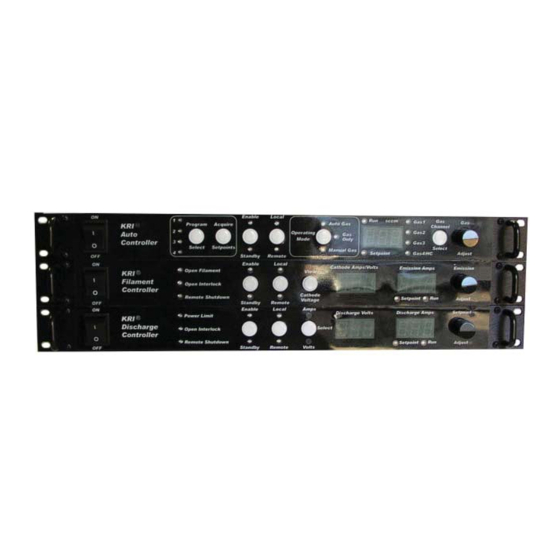
Page 9: Front View Of Controller For End Hall Ion Source
GENERAL DESCRIPTION AND SPECIFICATIONS GENERAL DESCRIPTION AND SPECIFICATIONS Fig. 2-1. Front view of controller for End Hall ion source. _______________________________________________________________________ Copyright © 2010 by Kaufman & Robinson, Inc., 1306 Blue Spruce Drive, Unit A, Fort Collins, CO 80524 Tel: 970-495-0187, Fax: 970-484-9350, Internet: www.ionsources.com... -
Page 10: Rear View Of Controller For End Hall Ion Source
GENERAL DESCRIPTION AND SPECIFICATIONS GENERAL DESCRIPTION AND SPECIFICATIONS Fig. 2-2. Rear view of controller for End Hall ion source. _______________________________________________________________________ Copyright © 2010 by Kaufman & Robinson, Inc., 1306 Blue Spruce Drive, Unit A, Fort Collins, CO 80524 Tel: 970-495-0187, Fax: 970-484-9350, Internet: www.ionsources.com... -
Page 11: Installation
INSTALLATION 3 INSTALLATION This section describes how to install the Kaufman & Robinson, Inc., KRI® Control- ler package for the fi lament cathode version of the End Hall Ion Source. 3.1 Unpack Unpack the Controller package for the End Hall Ion Source. Prior to shipment, the Controller was tested with the ion source to insure quality and verify the standard range of operation. -
Page 12: Install In Rack Mount Cabinet
INSTALLATION 3.2 Install in Rack Mount Cabinet The Controller is designed to be mounted in a standard 19-inch (48 cm) rack mount cabinet. To assure that the power cable that came with each controller is connected to that controller, the power cables can be connected as each controller is installed in the cabinet. - Page 13 INSTALLATION Controller. The individual connections required are given below: • If the 6 meter (20 ft.) input power supply cables were not connected to the individual power supplies when they were installed in the cabinet, connect them now. Use plugs that will match the input power sources. Again, do not connect to Input Power before the installation is complete.
- Page 14 INSTALLATION 3” and “MFC 4” located on the back panel of the Auto Controller. Attach the other ends of these cables to the corresponding MFC’s. • The mass fl ow controller is defi ned by the ion-source application. The gas fl...
-
Page 15: Connect Controller To Ion Source
INSTALLATION Description Number Not used. Not used. Chassis Ground. Not used. 3.5 Connect Controller to Ion Source If the Ion Source has not been installed in the vacuum chamber, do so now, using the Installation/Inspection description in the ion source manual. The ion source installation procedures cover installation of the ion source, vacuum cables, gas tubing inside the vacuum chamber, as well as electrical and gas feedthroughs in the wall of the vacuum chamber. - Page 16 INSTALLATION INSTALLATION Fig. 3-1. Front view of controller for End-Hall ion source. _______________________________________________________________________ Copyright © 2010 by Kaufman & Robinson, Inc., 1306 Blue Spruce Drive, Unit A, Fort Collins, CO 80524 Tel: 970-495-0187, Fax: 970-484-9350, Internet: www.ionsources.com...
- Page 17 INSTALLATION INSTALLATION Fig. 3-2. Rear view of controller for End-Hall ion source. _______________________________________________________________________ Copyright © 2010 by Kaufman & Robinson, Inc., 1306 Blue Spruce Drive, Unit A, Fort Collins, CO 80524 Tel: 970-495-0187, Fax: 970-484-9350, Internet: www.ionsources.com...
-
Page 18: Initial Operation
INITIAL OPERATION 4 INITIAL OPERATION This initial operation is done locally from the front panel and serves to both demon- strate and provide familiarization with operation. Make sure that the Auto controller is switched to local mode. When using the gas only mode described below, the fi... -
Page 19: Program Select
INITIAL OPERATION 4.3.1.1 Program Select The Auto controller is shipped with four programs stored. Pressing and releasing the white Program Select button will increment to the next program as indicated by the numbered red LED’s on the left side of the Program Select button. -
Page 20: Discharge Parameters
INITIAL OPERATION The emission setpoint can be adjusted by turning the Emission Adjust knob on the front of the Filament Power Supply. This can only be independently in the standby mode, but is also adjusted automatically when adjusting the Discharge current. This maintains the same Emission to Discharge current ratio. -
Page 21: Standby
INITIAL OPERATION 4.3.1.6 Standby Press and release the white Enable/Standby button on the front panel of the Auto Controller. Notice that the yellow Standby LED under the button turns on and the green Enable LED above the button turns off. The same LED transition from Enable to Standby also happens on the Filament Power Supply and the Discharge Power Supply as the Auto Controller sequences them off. -
Page 22: Saving A Program
INITIAL OPERATION scratchpad values will also be lost. If the Auto Controller is put into standby while the scratchpad is active, then the controller will run the scratchpad setpoints the next time the controller is enabled unless another program is selected before the controller is enabled 4.3.1.9 Saving a Program The fi... -
Page 23: Gas Only Mode
INITIAL OPERATION 4.3.2 Gas Only Mode When gas only mode is selected, the Auto Controller functions as a gas controller only. Independent control of the each of the four gas channels is possible. The description below outlines the use with one gas channel even though similar operation could be obtained using all the gas channels. - Page 24 INITIAL OPERATION Controller and then turn the Gas Adjust knob to 10 sccm. • Turn the knob on the Filament power supply until 2.7 amps is indicat- ed in the Emission Amps display. Note that the fi lament emission is usually set equal to or up to 10% greater than the discharge current.
-
Page 25: Constant Voltage Mode
INITIAL OPERATION • Put the Discharge and Filament power supplies into Standby in that order by pressing the white Enable/Standby button on each control- ler. • Put the gas fl ow into Standby by pressing the white Enable/Standby button on the auto controller. Restarting the ion source in the gas only mode consists of, enabling the Auto Controller, Filament Power Supply and Discharge Power supply in that order. -
Page 26: Manual Gas Mode
INITIAL OPERATION • Press the white Enable/Standby button on the Filament Power Sup- ply. • Press the white Enable/Standby button on the Discharge Power Sup- ply. • Adjust the gas fl ow using the Gas Adjust Knob on the Auto Controller until the discharge current is aproximatey 2.5 A. -
Page 27: Remote Enable/Standby
4-10 INITIAL OPERATION Select the Manual Gas mode using the Operating Mode button. Select the program to run using the Program Select button. Enable the program by pressing the Enable/Standby button on the Auto Controller. Press the Enable/Standby button again to stop the program and put the units into Standby. -
Page 28: Discharge Power Limit
INITIAL OPERATION 4-11 4.6 Discharge Power Limit The discharge power supply has a limit indicator LED. This power limit LED in- dicates possible overheating of the ion-source components. See the ion source manual for the power limit that is specifi c to the ion source being used. The limit can be setup as a passive indicator where only the Power Limit led fl... -
Page 29: General Operation
GENERAL OPERATION 5 GENERAL OPERATION The quickest way to start operation of the KRI Ion Source and its Controller is to follow the sequence described in Section 4, Initial Operation. This section gives a general overview of the ion source power supplies and there interconnection with the ion source. - Page 30 GENERAL OPERATION Filament Controller Auto Controller Discharge Controller Fig. 5-1. Schematic block diagram of ion source and controller. _______________________________________________________________________ Copyright © 2010 by Kaufman & Robinson, Inc., 1306 Blue Spruce Drive, Unit A, Fort Collins, CO 80524 Tel: 970-495-0187, Fax: 970-484-9350, Internet: www.ionsources.com...
-
Page 31: Remote/Automated Control
REMOTE/AUTOMATED CONTROL 6 REMOTE/AUTOMATED CONTROL The Auto controller has a variety of remote control options available. These options include a female DB-25 analog/digital interface, A DB-37 analog/digital interface and a DB-9 RS-232 serial interface. Note: The Auto Controller must be in Standby to switch between local and remote operating modes. -
Page 32: Pin Descriptions For The Female Db-25 Connector On The Auto Controller
REMOTE/AUTOMATED CONTROL Switch the front panel from local to remote and also connect pin 17 (Re- mote setpoint select) to pin 7 or 8 (common) on the DB-37. This selects the remote setpoints option for both the DB-25 and the DB-37 ports. The four stored programs are not available with the remote setpoint option. - Page 33 REMOTE/AUTOMATED CONTROL Description Number Source Lit Status: This output signal is used in conjunction with pin 21. When these two pins are shorted, it indicates that there is suffi cient anode current to consider the source started. If these two pins are open for a preset time while the source is running, it indicates that the source discharge has been lost.
-
Page 34: Remote Control Using The Db-37 Connector
REMOTE/AUTOMATED CONTROL 6.2 Remote Control using the DB-37 Connector The DB-37 connector is an extended control set which gives the operator full access to the Auto Controller inputs and outputs. There are two main options when using the DB-37 connector for remote control of the Auto Controller. One option is to enable one of the four programs stored in the auto controller. -
Page 35: Remote Analog Setpoint Option On The Db-37 Connector
REMOTE/AUTOMATED CONTROL of zero also de-energizes the gas relay on the rear panel and sends the valve off command to the mass fl ow controller. The gas relays are also de- energized and the valve off commands are sent to the mass fl ow control- lers when the Auto Controller is in standby. -
Page 36: Analog Outputs For The Db-37 Connector
REMOTE/AUTOMATED CONTROL maintain the program values for the discharge voltage and current, while maintaining the ratio established by the starting gas setpoints. Table 6-3. Pin descriptions for the analog inputs on the DB-37 connector. Description Number Discharge Voltage Setpoint. 0-5 volts corresponds with 0 to the maximum output voltage for the Discharge Power Supply. -
Page 37: Run Fault And Beam Good On The Db-37 Connector
REMOTE/AUTOMATED CONTROL Table 6-4. Pin descriptions for the analog outputs on the DB-37 connector. Description number Emission Current Output. 0-5 volts corresponds with 0 to the maximum emission current in amps for the Filament Power Supply. Referenced to pin 7 or 8. Filament Current Output. -
Page 38: Description Of The Db-37 Pins
REMOTE/AUTOMATED CONTROL A Run Fault occurs when the discharge fails to start or goes out. It also oc- curs if the operating parameters are out of range for more than 30 seconds. When a run fault occurs, the Auto Controller reverts to Standby and a help code or error message is displayed on the front panel of the Auto Control- ler. - Page 39 REMOTE/AUTOMATED CONTROL Description Number Emission Current Output. 0-5 volts corresponds with 0 to the maximum emission current in amps for the Filament Power Supply. Referenced to pin 7 or 8. Filament Current Output. 0-5 volts correspond with 0-40 amps of fi lament heating current for the Filament Power Supply.
- Page 40 6-10 REMOTE/AUTOMATED CONTROL Description Number DB-37 control select. The pin is connected to common pin 7 or 8 to enable the DB-37 connector. When the connection is left open, the DB-25 is active. Run Fault. When the Auto Controller is enabled, this pin will indicate a run fault if it is at a high logic level of 5 volts.
-
Page 41: Interlock
REMOTE/AUTOMATED CONTROL 6-11 Description Number No Contact No Contact Program Select 1. This pin is the 1 bit for selecting programs 1 through 4 using negative logic levels of 0 and 5 volts Acquire Setpoints. Hold for one second to remotely acquire program values applied to the DB-37 analog remote inputs. -
Page 42: Rs-232 Serial Interface
6-12 REMOTE/AUTOMATED CONTROL 6.4 RS-232 Serial Interface The RS-232 serial interface provides full remote control of the Auto Controller. The Remote/Local select on the front panel must be used to set the unit to re- mote to enable the remote control. 6.4.1 Interface cable The interface cable for the Auto controller must be a straight through type and must have a male DB-9 connector to connect to the female connector... -
Page 43: Vrb - Verbose Command
REMOTE/AUTOMATED CONTROL 6-13 auto controller. < > – Text inside arrow head brackets indicates parameters that are in- cluded with a command or command string. The brackets are not included when issuing the command. ( ) – Parentheses surround a numerical value or set point included in the command. -
Page 44: Com - Enable Rs-232 Command Or Status Query
6-14 REMOTE/AUTOMATED CONTROL Response: “OK” The RS-232 remote must be ‘Enabled’ as described in the next section before the issuing the VRB command. 6.4.4.2 COM - Enable RS-232 Command or Status Query The COM command will enable, disable or query the status of RS232 remote control of the auto controller depending on the parameter following it. -
Page 45: Idn? - Unit Identifi Cation Query
REMOTE/AUTOMATED CONTROL 6-15 If the unit is not in ‘Standby’ when this command is issued, if not the unit responds with: “Unit must be in STANDBY”. COM? – Query of remote control state. If the unit is in ‘Verbose’, the response is “Enabled” or “Disabled”. -
Page 46: Rst - Reset Command
6-16 REMOTE/AUTOMATED CONTROL 6.4.4.4 *RST – Reset Command The RST command will return to the unit to ‘Standby’ and clear any ‘recoverable’ error message(s). The unit will also be set to ‘Terse’ mode Command: *RST Example: *RST<cr><lf> Note: The only ‘recoverable’ errors are: HLP 10 –... -
Page 47: Mde - Mode Set Command Or Mode Query
REMOTE/AUTOMATED CONTROL 6-17 The OUT command ‘Enables’, ‘Disables’, or queries the output state of the system depending on the parameter following it. Command: OUT:<parameter> – To set the output state. Command: OUT? – To get the output state. Parameter/Response: 0 = Standby. 1 = Enabled. -
Page 48: Beam - Beam Good Query
6-18 REMOTE/AUTOMATED CONTROL Example: MDE:0<cr><lf> - Put unit in ‘Auto Gas’ If COM is active and unit is ‘Enabled’, the response of the unit is: “Unit must be in STANDBY”. If the COM is not ‘Enabled’, the command is ignored both in ‘Terse’... - Page 49 REMOTE/AUTOMATED CONTROL 6-19 mand can be used to set or query the values for individual parameters or for a string of parameters depending on the format of the command. The general form of the program read/write command is: Command: P<program#>:<parameter> (value) The <parameter>...
- Page 50 6-20 REMOTE/AUTOMATED CONTROL GS1 – Gas Channel 1, xxx.x GS2 – Gas Channel 2, xxx.x GS3 – Gas Channel 3, xxx.x GS4 – Gas Channel 4, xxx.x DSV – Discharge Voltage Target, xxx.xxx DSI – Discharge Current Target, xx.xxx BEI – Filament Emission Current Target, xx.xxx The (values) for each <parameter>...
- Page 51 REMOTE/AUTOMATED CONTROL 6-21 In using the ALL parameter to set targets, the list of values must be comma delimited and appear in the order shown. Any value that is to remain unchanged can be omitted, but the comma delimiter between parameters must be included in the input string. In the second example, DSI remains unchanged in the target program.
- Page 52 6-22 REMOTE/AUTOMATED CONTROL Example: P1:DSV 200 – Set the Discharge voltage for program 1 to 200 volts. If the auto controller is in the ‘Auto Gas’ mode, then the setpoint cur- rent (DSI) will be the setpoint Discharge current. The gas fl ow will be the starting fl...
-
Page 53: Feedback Values
REMOTE/AUTOMATED CONTROL 6-23 It is very important to understand the operating limits of the Ion Source to prevent damage. Review the ion source manual to determine appropriate operating conditions. Contact KRI for assistance in establishing operating conditions if necessary. 6.4.4.10 R - Monitor Command for Reading the Actual Feedback Values The R command is used to get the actual feedback values from the auto controller. -
Page 54: Lrn - Learn Command Or Learn Query
6-24 REMOTE/AUTOMATED CONTROL Command: CFG? In VERBOSE, the responses are: “Filament” “Hollow Cathode with BV” “Hollow Cathode without BV” “Gas Only” “Unknown” In ‘TERSE’, the responses are: “0”, “1”, “2”, “3” or “4”, respectively. 6.4.4.12 LRN – Learn Command or Learn Query The current status of LRN can be queried any time. -
Page 55: Diagnostics
DIAGNOSTICS 7 Diagnostics The following information is intended to facilitate troubleshooting of the Auto Con- troller and associated power supplies. This information assumes that the Auto Controller and power supplies are connected to power and that all interconnects between power supplies and the ion source cable are made correctly. It is also assumed that all gas connections are in good condition and that the gas circuit is complete from the gas bottle to the ion source. - Page 56 DIAGNOSTICS Help Code Description Possible Causes And Corrective Action or Error Message RS-232 Interface Serial Common Error. - High Informational display only. No current fl owing in the action taken on unit operation. ground connection of the Unit recovers from error condi- serial interface between HLP 8 tion if problem goes away.
- Page 57 DIAGNOSTICS Help Code Description Possible Causes And Corrective Action or Error Message Press and release the STAND- BY/ENABLE button or remove the remote enable signal to clear the code. The unit remains in STANDBY until STANDBY/ ENABLE is pressed again or the remote enable signal is reap- plied.
-
Page 58: Filament Power Supply
DIAGNOSTICS Help Code Description Possible Causes And Corrective Action or Error Message Press and release the STAND- BY/ENABLE button or remove the remote enable signal to clear the code. The unit remains in STANDBY until STANDBY/ ENABLE is pressed again or the remote enable signal is reap- plied. - Page 59 DIAGNOSTICS Help Code Description Possible Causes And Corrective Action or Error Message Press and release the STAND- BY/ENABLE button or remove the remote enable signal to clear the code. The unit remains in STANDBY until STANDBY/ ENABLE is pressed again or the remote enable signal is reap- plied.
- Page 60 DIAGNOSTICS Help Code Description Possible Causes And Corrective Action or Error Message Press and release the STAND- BY/ENABLE button or remove the remote enable signal to clear the code. The unit remains in STANDBY until STANDBY/ ENABLE is pressed again or the remote enable signal is reap- plied.
-
Page 61: Help Codes And Error Messages For The Filament Power Supply
DIAGNOSTICS action that may need to be taken. Table 7-2. Help codes and error messages for the Filament Power Supply. Help Code Description Possible Causes or Error and Corrective Message Action Current Latch – A high current was encountered. Switch off the power until the HLP 1 Power supply latched off to display is dark and then switch... -
Page 62: Discharge Power Supply
DIAGNOSTICS Help Code Description Possible Causes or Error and Corrective Message Action RS-232 Interface Serial Informational display only. No ac- Common Error. - High cur- tion taken on unit operation. Unit rent fl owing in the ground recovers from error condition if connection of the serial the problem goes away. - Page 63 DIAGNOSTICS Help Code Description Possible Causes or Error and Corrective Message Action Current Latch – A high Switch off the power until the current was encountered. HLP 1 display is dark and then switch Power supply latched off to the power back on to reset prevent a failure.
-
Page 64: Limited Warranty
LIMITED WARRANTY 8 LIMITED WARRANTY Kaufman & Robinson, Inc. (KRI) warrants to the purchaser or end user of the equip- ment it sells that such equipment will be free from defects in material and work- manship under normal use and service. This warranty is for a period of fi fteen (15) months from the date of original shipment F.O.B KRI’s facility, Fort Collins, Colo- rado, or one year from the date the equipment is placed in use by the purchaser or end user thereof, whichever occurs fi... -
Page 65: Service And Technical Information
SERVICE AND TECHNICAL INFORMATION 9 SERVICE AND TECHNICAL INFORMATION For technical information, repairs or replacement during Warranty, or repairs there- after, please contact: Kaufman & Robinson, Inc. 1306 Blue Spruce Dr. Unit A Fort Collins, CO 80524 Tel.: 970-495-0187 Fax.: 970-484-9350 Internet: www.ionsources.com Please include the following details relating to the problem encountered or the item to be returned:...
Need help?
Do you have a question about the eHF 3005A and is the answer not in the manual?
Questions and answers