Table of Contents
Advertisement
Quick Links
Advertisement
Table of Contents

Related Manuals for ROMANOFF ELETTROLASER MS 3.5


Summary of Contents for ROMANOFF ELETTROLASER MS 3.5
- Page 1 SINCE 1949 1/19/24 Romanoff.com • Sales@romanoff.com • 631-842-2400 Page 1 of 112...
- Page 2 ElettroLaser MS 3.5 & MS 165 User Manual 1/19/24 Romanoff.com • Sales@romanoff.com • 631-842-2400 Page 2 of 112...
-
Page 3: General Index
ElettroLaser MS 3.5 & MS 165 User Manual General index Tittle Page General index ....................... 3 Warranty and liability ....................4 Use of the manual ......................6 General instructions...................... 9 Characteris�cs and technical data ................25 Transport and installation .................... 34 Opera�on ........................ -
Page 4: Warranty And Liability
ElettroLaser MS 3.5 & MS 165 User Manual Warranty and liability Warranty This Warranty covers the product it accompanies at the �me of purchase. This Warranty guarantees the product against any material or manufacturing faults for a period of THREE YEARS from the original date of purchase. -
Page 5: Reserved Legal Rights
ElettroLaser MS 3.5 & MS 165 User Manual Compromised functioning or breakdowns of the product or of associated products due to defects or lack of availability while • under assessment in the facilities of Ele�rolaser or other authorized support centers, with consequent down�me, loss of production �me or interruptions in opera�ons;... -
Page 6: Use Of The Manual
ElettroLaser MS 3.5 & MS 165 User Manual Use of the manual This manual was prepared by the Manufacturer and is an integral part of the supply of the machinery. The informa�on featured in the MS 3.5, manual addresses the staff in charge of operating and maintaining the machine. -
Page 7: Structure Of The Manual
ElettroLaser MS 3.5 & MS 165 User Manual Structure of the manual 3.2.1 Division of the manual This manual is divided into chapters. Each chapter may in turn be divided into paragraphs. The lower external margin of each page indicates the page number and the total number of pages in the manual. -
Page 8: Conserva�On Of The Manual
ElettroLaser MS 3.5 & MS 165 User Manual Conserva�on of the manual 3.4.1 How to conserve the manual This manual, the original copy of the declara�on of conformity and all the technical annexes must be stored with care for the en�re lifespan of the machine, including the disassembly phase. -
Page 9: General Instruc�Ons
ElettroLaser MS 3.5 & MS 165 User Manual General instructions Working in safe condi�ons Safety instructions included in the user and maintenance manual refer to opera�ons which can be performed on the machine. Safety symbols are included in the text to highlight items which require par�cular a�ention. It is essen�al that these safety instructions be observed at all times. -
Page 10: Symbols Used
ElettroLaser MS 3.5 & MS 165 User Manual Symbols used The following symbols are used in this manual. These symbols have been included to help understand performed / described ac�vities; they are generally featured in paragraphs 7.4 and 7.5 and in chapters 8 and 9. -
Page 11: Hazard Signs
ElettroLaser MS 3.5 & MS 165 User Manual 4.3.1 Hazard signs Generic hazard This sign is used to highlight hazardous situations which may cause damage to persons, animals and things. Failure to observe instructions associated with this sign can cause danger. -
Page 12: Prohibi�On Signs
ElettroLaser MS 3.5 & MS 165 User Manual 4.3.2 Prohibition signs Generic prohibition This sign is used to highlight that certain maneuvers, opera�ons or forms of behavior are not permi�ed. Failure to observe instructions associated with this sign can cause damage to things, animals, persons. -
Page 13: Obliga�On Signs
ElettroLaser MS 3.5 & MS 165 User Manual 4.3.3 Obligation signs Generic obligation This sign is used to highlight that the operator must observe the specific instructions. Failure to observe instructions associated with this sign can cause damage to things, animals, persons. -
Page 14: General Informa�On On Classifica�On Of Lasers
ElettroLaser MS 3.5 & MS 165 User Manual General informa�on on classifica�on of lasers Classifica�on of lasers follows this standard: CEI EN 60825-1: 2014 Safety of laser products Part 1: Classifica�on of devices and requirements. • 4.4.1 Hazard potential of laser classes The concept of laser is insufficient to describe the hazard presented by a device emi�ing coherent electromagne�c radia�on. - Page 15 ElettroLaser MS 3.5 & MS 165 User Manual In general, in the case of exposures exceeding the threshold, the predominant mechanism mainly depends on the dura�on of the exposure pulse. Thus, following an ascending order of dura�on of the pulse, the predominant effects in the following time intervals are: For exposures lasting nanoseconds and lower than one nanosecond, micro-cavita�on, transitory acous�c events and non-linear...
-
Page 16: Hazards To The Eyes
ElettroLaser MS 3.5 & MS 165 User Manual 4.5.2 Hazards to the eyes 4.5.2.1 Physiology of the eye Eyebrows Light Cornea (transparent front part Eyelashe Blood vessels of eye) Eyelid Aqueous humour Sclera (white part Lens Receptor cells of eye) -
Page 17: Pathological Effects Of Laser Radia�On
ElettroLaser MS 3.5 & MS 165 User Manual 4.5.3 Pathological effects of laser radiation 4.5.3.1 Hazards to the eyes Fig. 4-2 features a brief description of the anatomy of the eye. The eye is par�cularly well-suited to receiving and transmitting op�cal radia�on. -
Page 18: Classifica�On And Specific Hazards Of Radia�On Emi�Ed By Ms 3.5
ElettroLaser MS 3.5 & MS 165 User Manual Classifica�on and specific hazards of radia�on emi�ed by MS 3.5 Based on the CEI EN 60825-1: 2014 standard, MS 3.5 is classified as indicated in the following Tab. 4-3: Parameter Value Laser class... -
Page 19: Graphic Signs And Wri�En Warnings
ElettroLaser MS 3.5 & MS 165 User Manual Graphic signs and wri�en warnings Please find below the graphic signs and written warnings located on the machine. These signs were inserted to make the operator aware of hazards or residual poten�al sources of danger. An explanatory comment can be found next to each exclusively graphic sign. -
Page 20: Obliga�On Graphic Signs And Wri�En Warnings
ElettroLaser MS 3.5 & MS 165 User Manual This sign highlights the hazard (residual risk) associated with exposure of the eyes and skin to direct or diffuse radia�on, and furthermore provides informa�on on the characteristics of the laser source Fig. 4-7 – Warning label 4.7.2... -
Page 21: Posi�On Of Graphic Signs And Written Warnings
ElettroLaser MS 3.5 & MS 165 User Manual 4.7.4 Position of graphic signs and written warnings Fig. 4-10 - Posi�on of graphic signs and wri�en warnings – le� side view Fig. 4-12 - Posi�on of graphic signs and wri�en warnings – right side Fig. -
Page 22: Physical And Intellectual Requirements Of Personnel
ElettroLaser MS 3.5 & MS 165 User Manual Physical and intellectual requirements of personnel The personnel must be capable – also on a physical level – of performing necessary opera�ons and of familiarizing with instructions and safety laws. This staff will have been trained (according to performed/assigned tasks) to be able to safely use the machine and/or to perform maintenance operations on the machinery in safe condi�ons. -
Page 23: Staff In Charge Of Extraordinary Maintenance (Support Service)
ElettroLaser MS 3.5 & MS 165 User Manual 4.10 Staff in charge of extraordinary maintenance (support service) In terms of maintenance staff, standard EN 15628 (Maintenance – Qualifica�on of maintenance personnel) identifies the following three professional figures and defines their correspondent necessary skills: Maintenance manager (indicatively referable to EQF levels 6 and 7 •... -
Page 24: Laser Safety Officer
ElettroLaser MS 3.5 & MS 165 User Manual 4.11 Laser safety officer In many countries, in case of class 3B or 4 laser products, the employer must appoint a LASER SAFETY OFFICER. Consult local laws in this regard. 4.12 Staff in charge of opera�ng the machine The machine must be run by a professional operator, as described under paragraph 5.4, which also describes his/her posi�on and... -
Page 25: Characteris�Cs And Technical Data
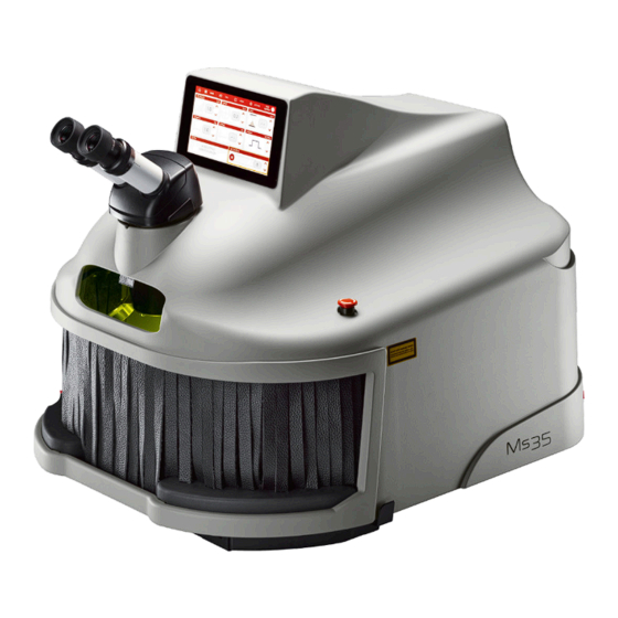
ElettroLaser MS 3.5 & MS 165 User Manual Characteris�cs and technical data Descrip�on of the machine MS 3.5 (Fig. 5-1 and Fig. 5-2) is a welding machine for artefacts made of metallic materials that uses electromagnetic laser radiation as an energy source for hea�ng metals to melting temperature. -
Page 26: Applicable Technical Regula�Ons And Laws
ElettroLaser MS 3.5 & MS 165 User Manual Applicable technical regulations and laws The machine was designed in observance of the following Community rules on the safety of the machinery and laser system products: EN ISO 12100:2010 Safety of machinery - General principles for design - Risk assessment and risk reduc�on;... -
Page 27: Residual Risks
ElettroLaser MS 3.5 & MS 165 User Manual Residual risks The machine requires the prepara�on of work stations as indicated in the following Tab. 5-1: Work station N° of operators Opera�ons In front of the machine 1 operator Welding Tab. 5-1 –... - Page 28 ElettroLaser MS 3.5 & MS 165 User Manual Parameter Risks P.P.E. * Risk of electrocution and electric shock: the machine is powered by electricity, and therefore opera�ons on live or disconnected electrical parts must be performed exclusively by the specifically responsible technician, in observance of all necessary precau�ons (EN 50110-1).
-
Page 29: Technical Data Of The Machine
ElettroLaser MS 3.5 & MS 165 User Manual Technical data of the machine 5.5.1 Technical data Parameter Description MS 3.5 Dimensions Minimum length of installa�on area 2600 mm Minimum width of installa�on area 2900 mm Minimum height of installa�on area... -
Page 30: Noise Levels
ElettroLaser MS 3.5 & MS 165 User Manual Parameter Description MS 3.5 Maximum emi�ed power or energy MS 3.5 (35 J): 3 kW MS 3.5 (80 J): 4 kW MS 3.5 (165 J): 6,5 kW Average Power MS 3.5 (35 J; 80 J):... -
Page 31: Vibra�Ons
ElettroLaser MS 3.5 & MS 165 User Manual WARNING!: The acoustic impact produced by the machine in the surrounding environment can be considered of li�le relevance in test conditions. In any case, it is important to keep in mind that the level of exposure of the operator in charge of running the machine will have to be assessed in the actual operating conditions of the machine, in conformity with current legislation (of the country where the machine is placed on the market). -
Page 32: Product Characteris�Cs
ElettroLaser MS 3.5 & MS 165 User Manual Product characteris�cs 5.6.1 Technical characteristics of workable products The products to be processed (an example is shown in Fig. 5-3) consist of products for the goldsmith/jewelry sector, such as, for example: jewels and glasses, watches and bracelets Fig. -
Page 33: Weld Materials
ElettroLaser MS 3.5 & MS 165 User Manual WARNING!: Make sure that the metals to be processed feature no impurities which may cause the formation of smoke or gas during the melting stages. 5.6.2 Weld materials If required by the type of welding in ques�on, the operator can use weld materials such as silver, monel, steel, cobalt-chromium alloy and �tanium... -
Page 34: Transport And Installa�On
ElettroLaser MS 3.5 & MS 165 User Manual Transport and installation ransport The machine and all the provided parts are usually supplied fully packaged in a cardboard box. During transporta�on, the box is fastened to a transport pallet; in the case of transporta�on via airplane, the box is in turn packaged within a wooden crate. -
Page 35: Manual Handling Of Loads
ElettroLaser MS 3.5 & MS 165 User Manual Manual handling of loads Manual handling of loads (MHL) must be carried out in safe condi�ons to avoid overloading the dorsal-lumbar tract of the spine. Please find below a series of safety instructions concerning manual handling of loads. - Page 36 ElettroLaser MS 3.5 & MS 165 User Manual Fig. 6-3 – Handling technique Keep the load as close as possible to your body; • Distribute the load on both sides; • Keep your view clear; • Ensure at least two operators manage the li�ing of bulky loads (Fig. 6-4);...
-
Page 37: Installa�On
ElettroLaser MS 3.5 & MS 165 User Manual Installation WARNING!: Before proceeding with installation of the machine, carefully read the instructions below. Failure to observe the following warnings can cause injuries, death or damage to equipment. ELETTROLASER S.R.L. declines any liabilities for damage to persons or things due to installation in an environment characterized by one of the situations described below. - Page 38 ElettroLaser MS 3.5 & MS 165 User Manual machine) located directly on the worktable, under the machine (as schema�cally illustrated in Fig. 6-5), and corresponding with the product smoke output grid (Fig. 6-6). Suc�on vent hole Fig. 6-5 – Ideal installation on worktable WARNING!: Welding operations produce smoke and gas: breathing these can be harmful for human health.
-
Page 39: Assembly
ElettroLaser MS 3.5 & MS 165 User Manual Assembly The machine is supplied fully assembled. To install the machine, proceed as follows: Place MS 3.5 on the work surface (please also refer to paragraph 6.6), so that: • It is leaning all four feet (Fig. 6-6);... -
Page 40: Start Up
ElettroLaser MS 3.5 & MS 165 User Manual Connect the control pedal of the machine: • Connect the male connector of the trigger control pedal to the female DB-9 female serial port (Fig. 6-8), located on the rear ▪ of the machine;... -
Page 41: Connec�On To The Electrical Network
ElettroLaser MS 3.5 & MS 165 User Manual Connec�on to the electrical network 6.9.1 Instructions WARNING!: The machine must be connected to the grounding system. Grounding continuity must be ensured for all electrical equipment. For this purpose, the client must supply the connection points for the grounding system of the building, making sure the system is compliant with requirements set forth by current legislation. -
Page 42: Protec�On From Electric Shocks
ElettroLaser MS 3.5 & MS 165 User Manual 6.9.3 Protection from electric shocks 6.9.3.1 Direct contact Direct contact is when “persons or animals come in contact with live parts”, i.e. with dangerous voltage levels (EN 60204-1). All electrical devices are inserted within specific casings for electrical material, which require a tool to be opened. -
Page 43: Shield Gas
ElettroLaser MS 3.5 & MS 165 User Manual 6.10 Shield gas OBLIGATION!: This opera�on can only be performed by the dealer / authorized installation technician! MS 3.5 can be set up for use with a shield gas (argon), an ideal choice when welding materials such as �tanium, to protect the material from oxida�on and improve welding quality. - Page 44 ElettroLaser MS 3.5 & MS 165 User Manual Use only regulation tanks and pressure reducers, tubes and connections that have been approved for this specific use; keep • these elements and all connected parts in good conditions; Do not expose your face to the output valve of the tank when open;...
-
Page 45: Further Connec�Ons
ElettroLaser MS 3.5 & MS 165 User Manual 6.11 Further connec�ons The machine features further connection points, such as: A USB port (op�onal) for connection to storage devices. • Furthermore, the machine features a Wi Fi antenna, for connection to a wireless network USB port Fig. -
Page 46: Management Of Machine Keys
ElettroLaser MS 3.5 & MS 165 User Manual 6.12 Management of machine keys The keys of the machine (interlock bypass connector and igni�on key) are delivered separately. These keys must be managed by the Laser Safety Technician (LST). Before ac�va�ng the machine, the interlock contact must be connected to the safety system set up in the site where the machine is installed. -
Page 47: Opera�On
ElettroLaser MS 3.5 & MS 165 User Manual Operation Machine operation MS 3.5 (Fig. 7-1) is a welding machine for artefacts made of metallic materials that uses electromagne�c laser radia�on as an energy source for hea�ng metals to melting temperature. - Page 48 ElettroLaser MS 3.5 & MS 165 User Manual Op�cal resonator Ac�ve medium Laser beam Totally Par�ally reflec�ve mirror reflec�ve mirror Pumping system Fig. 7-2 – Opera�ng principle 1/19/24 Romanoff.com • Sales@romanoff.com • 631-842-2400 Page 48 of 112...
-
Page 49: Specific Glossary
ElettroLaser MS 3.5 & MS 165 User Manual 7.1.2 Specific glossary The following Tab. 7-1 features defini�ons of specific laser applica�on terminology, for the purpose of making the contents of this manual more comprehensible Term Definition Aperture, diaphragm Aperture means any opening in the laser device protective casing through which the laser radia�on is emi�ed, thus allowing... - Page 50 ElettroLaser MS 3.5 & MS 165 User Manual Term Definition Workpiece Object to be processed with laser radia�on. Tab. 7-1 – Specific glossary 1/19/24 Romanoff.com • Sales@romanoff.com • 631-842-2400 Page 50 of 112...
-
Page 51: Machine Body
ElettroLaser MS 3.5 & MS 165 User Manual 7.1.3 Machine body The body of the machine (Fig. 7-3) consists of an injec�on molded technopolymer casing. The casing is closed with screws. It contains the laser source (lamp and resonator), all power and control devices for the laser source, the coolant system, the laser channeling and focus unit and the resonator shu�er (a shu�er controlled by an electromagnet, which... -
Page 52: Stereomicroscope Vision System
ElettroLaser MS 3.5 & MS 165 User Manual 7.1.4 Stereomicroscope vision system The work area can be visualized via binocular stereoscopic microscope. The vision system consists of an op�cal magnifica�on system that allows the operator to focus on the laser target during welding opera�ons. -
Page 53: Welding Chamber
ElettroLaser MS 3.5 & MS 165 User Manual 7.1.5 Welding chamber The welding chamber is incorporated within the welding machine casing. The access compartment of the welding chamber (Fig. 7-3), is closed by a sector curtain with the function of containing the laser radia�on, as this may be diffused or reflected during welding opera�ons (e.g. - Page 54 ElettroLaser MS 3.5 & MS 165 User Manual The op�cal path is the channel through which the laser beam is introduced to the chamber. This channel is closed by a protection glass (Fig. 7-8) which protects the op�cal path from fused par�cle projec�ons which may take place during welding operations.
-
Page 55: Control Device
ElettroLaser MS 3.5 & MS 165 User Manual Control device The following figures (Fig. 7-9, Fig. 7-10, Fig. 7-11) ) illustrate the control and emergency devices installed on MS 3.5 and described in Tab. 7-2. Display touch Emergency switch screen... - Page 56 ElettroLaser MS 3.5 & MS 165 User Manual CONTROL DEVICES Posi�on Descrip�on General power switch: O: the machine is disconnected from the electrical power supply; • Fig. 7-9 I: the machine is electrically powered. • Jack-type key switch (igni�on key) allowing the operator to select the following controls: laser off –...
-
Page 57: Operator Interface
ElettroLaser MS 3.5 & MS 165 User Manual 7.2.1 Operator interface In addition to the devices men�oned above, the machine also features an operator interface (Fig. 7-12). The interface features a touch terminal (7” color touch screen display) which allows the operator to set the various operational parameters. -
Page 58: Safety Devices
ElettroLaser MS 3.5 & MS 165 User Manual Safety devices The machine features a series of safety devices, illustrated in the following paragraphs 7.3.1 Emergency bu�ons When pressed, the emergency bu�ons (Fig. 7-13), allow the operator to stop the machine in the event of emergencies. -
Page 59: Interlock
ElettroLaser MS 3.5 & MS 165 User Manual 7.3.2 Interlock The interlock (Fig. 7-14) is a safety device (that must be activated before using the machine for the first time); failure to activate this device will block the laser and therefore stop MS 3.5 from operating. -
Page 60: Ac�Va�On Key
ElettroLaser MS 3.5 & MS 165 User Manual 7.3.3 Enabling key The enabling key (Fig. 7-15) allows the operator to turn the machine on for use. The key can be removed, and so the machine goes to the LOCK status, and must always be removed from the machine if le� una�ended, to avoid use by unauthorized staff Igni�on key... -
Page 61: Microscope Shu�Er
ElettroLaser MS 3.5 & MS 165 User Manual 7.3.5 Microscope shutter This device consists of a liquid crystal (LCD) filter that, when subjected to a specific tension, turns completely dark. It is located between the 45° mirror and the focus lens of the microscope. - Page 62 ElettroLaser MS 3.5 & MS 165 User Manual Fixed guard - case Fixed guard – smoke extraction ventilator protection grid Flexible shield – Fixed guard – segmented leather ven�la�on grid blind Fig. 7-16 – Guards Fixed guard – ven�la�on grid Fig.
-
Page 63: Preliminary Opera�Ons
ElettroLaser MS 3.5 & MS 165 User Manual Preliminary operations 7.4.1 Insertion of the cooling liquid The cooling liquid (dis�lled and deionized water) is required to cool the laser source. The machine is supplied with a container featuring the correct quan�ty of cooling liquid OBLIGATION!: Use only the cooling liquid container supplied with the machine. - Page 64 ElettroLaser MS 3.5 & MS 165 User Manual If Error 02 TEST FLUX H20 occurs, purge any air bubbles inside the circuit: ▪ Power up the machine (see paragraph 8.3); ▪ If the operator panel displays the warning message “ERROR 02 TEST FLUX H2O”, remove the key - OFF and repeat the ▪...
-
Page 65: Preliminary Regula�On Opera�Ons
ElettroLaser MS 3.5 & MS 165 User Manual Preliminary regulation opera�ons WARNING!: Failure to perform preliminary regulation opera�ons can cause damage to the machine and/or installed equipment. WARNING!: All preliminary regulation operations must be performed with the machine switched off. -
Page 66: Opera�On Instruc�Ons
ElettroLaser MS 3.5 & MS 165 User Manual Operation instructions Safety instruc�ons WARNING!: Failure to observe the following safety instructions may result in injuries, death or damage to the machine. This machine must be operated exclusively by “qualified staff”, based on the correspondent indications included in this manual. -
Page 67: Non Permissible Opera�Ons
ElettroLaser MS 3.5 & MS 165 User Manual Non permissible operations 8.1.4 The following uses of the welding machine are explicitly prohibited: The MS 3.5 welding machine is designed for professional use. • Use of the welding machine when it presents signs of tampering or damage (in particular cracks in the casing and protec�on •... -
Page 68: Prepara�On For Start-Up
ElettroLaser MS 3.5 & MS 165 User Manual Electrostatic charges that are still present a�er switching off the machine; • Hot parts of the machine. • Preparation for start-up Before star�ng MS 3.5 you must make sure that the electrical system of the building where the machine is installed is ac�vated. -
Page 69: Start-Up
ElettroLaser MS 3.5 & MS 165 User Manual Start-up 8.4.1 Operation A�er switching MS 3.5 on (power up), you need to enable its opera�on (insertion). To enable MS 3.5 to operate, please follow the sequence of opera�ons described in the following Tab. 8-2. - Page 70 ElettroLaser MS 3.5 & MS 165 User Manual 8.4.1.1 Welding set�ngs MS 3.5 can store up to 100 (one hundred) different work programs. In any case, we recommend the following welding settings (Tab. 8-3), based on the materials requiring welding.
-
Page 71: Operator Panel
ElettroLaser MS 3.5 & MS 165 User Manual Operator panel This paragraph describes all the se�ngs that can be edited by using the operator interface (operator panel). The operator panel terminal is a “touch screen” (or tac�le terminal), allowing the operator to send commands and/or edit machine se�ings by simply using his/her finger to press the control areas on the terminal corresponding to the chosen command. -
Page 72: Menu Bar
ElettroLaser MS 3.5 & MS 165 User Manual 8.5.1 Menu bar The upper part of the operator panel pages (with a few excep�ons) features a menu bar which allows the operator to promptly access the main pages Fig. 8-1 – Menu bar When pressed, this control area allows the operator to access the “Home”... -
Page 73: Home" Page
ElettroLaser MS 3.5 & MS 165 User Manual 8.5.2 “Home” page “Home” page Fig. 8-2 – When pressed, this control area allows the operator to access the “Language” se�ings page. This page (Fig. 8-3) allows the operator to set the language of all texts on the pages and on the alphanumeric keyboard for data input. -
Page 74: Laser" Opera�On Set�Ngs Page
ElettroLaser MS 3.5 & MS 165 User Manual 8.5.3 “Laser” operation settings page “Laser” opera�on se�ings page Fig. 8-5 – This display area shows the power, in kilowa�s, of the welding shot set for the selected welding program; the stored ID number of the program is indicated under item 8. - Page 75 ElettroLaser MS 3.5 & MS 165 User Manual This control area displays the ID number of the welding program (in the memory index) the machine is currently set to perform. In addition to this number, the display shows the name associated with this program, which generally corresponds to the type of metal requiring welding.
-
Page 76: Video" Page
ElettroLaser MS 3.5 & MS 165 User Manual 8.5.4 “Video” page This page allows the operator to watch tutorial videos on how to use the machine or how to perform a series of maintenance opera�ons, pre-uploaded to the internal storage of the machine). -
Page 77: Se�Ngs Page
ElettroLaser MS 3.5 & MS 165 User Manual 8.5.5 Settings page Fig. 8-8 – Se�ngs page View-only area displaying: The par�al number of shots generated by the machine: rese�ed when the lamp is changed by the technical service; • The total number of total shots generated by the machine;... - Page 78 ElettroLaser MS 3.5 & MS 165 User Manual 8.5.5.1.1 Data logger Fig. 8-9 – Pagina data logger Selec�on area of the day to be analysed. Selec�on areas of the month to analyze. Selec�on area of the year to be analysed.
- Page 79 ElettroLaser MS 3.5 & MS 165 User Manual 8.5.5.1.2 Alarm History Fig. 8-10 – Pagina storico allarmi Alarm log display area. Command area which, if pressed, allows you to return to the "Se�ngs" page (paragraph 8.5.6). 1/19/24 Romanoff.com • Sales@romanoff.com • 631-842-2400...
- Page 80 ElettroLaser MS 3.5 & MS 165 User Manual 8.5.5.2 Parameters page Fig. 8-11 – Parameters page This display area shows the idle time, in minutes, a�er which – unless the pedal is pressed – the machine will automa�cally shi� into stand-by mode (the resonator shu�er will ac�vate and interrupt the laser path).
- Page 81 ElettroLaser MS 3.5 & MS 165 User Manual 8.5.5.3 Warning messages The following table (Tab. 8-4) lists the warnings flagged by the machine. For each warning, the table includes the warning text displayed on the operator panel, the possible cause for the warning and, when applicable, the opera�ons required to restore the machine to normal condi�ons.
- Page 82 ElettroLaser MS 3.5 & MS 165 User Manual # Warning message Possible cause Troubleshooting operations Error 05 TEST RELAY The machine is on but does not weld: Check the connection to the electrical grid; Power supply issues. Replace the electrical power cable.
- Page 83 ElettroLaser MS 3.5 & MS 165 User Manual 8.5.5.4 Memory set page The machine can store up to 100 memory indexes Memory set page Fig. 8-12 – Numeric keyboard for input�ng the program (memory index) number. Pressing the control areas will update the value displayed under item 3.
- Page 84 ElettroLaser MS 3.5 & MS 165 User Manual 8.5.5.5 Date/time se�ings page Fig. 8-13 – Date/time se�ngs page This display area shows the day. Next to this area you will find the controls that, when pressed, allow the operator to increase (+) or decrease (-) the set value by one unit.
- Page 85 ElettroLaser MS 3.5 & MS 165 User Manual 8.5.5.6 So�ware management page Fig. 8-14 – So�ware management page View-only area displaying the interface messages indicating the opera�ons required to proceed with the update. When pressed, this control area allows the operator to start a teleassistance connection.
- Page 86 ElettroLaser MS 3.5 & MS 165 User Manual 8.5.5.7 Network settings page The machine can be connected to an Ethernet and/or Wi Fi network. The RJ45 socket (Fig. 6-13) is located on the rear of the machine. Network se�ngs page (Ethernet) Network se�ngs page (Wi Fi)
-
Page 87: How To Stop The Machine
ElettroLaser MS 3.5 & MS 165 User Manual How to stop the machine 8.6.1 Introduction Please find below details on opera�ons required to stop the machine. The opera�ons described below are the only ones permi�ed by the manufacturer 8.6.2 Standby The machine will automa�cally suspend laser opera�ons (the resonator shu�er ac�vates, interrupting the laser path, and the... -
Page 88: Troubleshoo�Ng
ElettroLaser MS 3.5 & MS 165 User Manual Troubleshooting The following table (Tab. 8-7) lists a series of potential issues which may take place (due to incorrect use / opera�ons with MS 3.5 and/or due to machinery faults) and cause: Inadequate processing quality (and consequently insufficient quality of the product);... -
Page 89: Maintenance
ElettroLaser MS 3.5 & MS 165 User Manual Maintenance Maintenance safety rules OBLIGATION!: All EXTRAORDINARY maintenance opera�ons must be performed exclusively by qualified ELETTROLASER S.R.L. staff (please refer to paragraph 4.8) or staff authorized by this company, with the necessary technical know-how to perform these operations in conditions of maximum safety and in full compliance with currently effective regulations and laws on the subject. -
Page 90: Welding Chamber Infrared Filter
ElettroLaser MS 3.5 & MS 165 User Manual WARNING!: The absence of safety signs can expose the worker to hazards, as he/she may not perceive the presence of any residual risks. 9.2.2 Welding chamber infrared filter The infrared filter of the welding chamber inspection window must always be checked visually (making sure of its functional integrity) every time the machine is used. -
Page 91: Replacement Of The Special Protec�On Glass
ElettroLaser MS 3.5 & MS 165 User Manual 9.2.4 Replacement of the special protection glass Whenever the special protection glass is “dirty”, its performance will decrease; thus, whenever a significant concentration of metal sprays hits its surface, the glass will need to be replaced. -
Page 92: How To Align The Re�Cle Pointer Of The Binocular
ElettroLaser MS 3.5 & MS 165 User Manual 9.2.5 How to align the reticle pointer of the binocular The re�cle pointer may some�mes not be aligned with the actual shot point. This can occur when the welding machine is moved or lifted. - Page 93 ElettroLaser MS 3.5 & MS 165 User Manual Screw 1 for calibra�on Screw 2 do not touch Screw 3 for calibra�on Calibra�on of re�cle pointer alignment Fig. 9-3 – WARNING!: During alignment operations, pay a�ention to the position of your hands, as they may interfere with the passing of the laser beam.
-
Page 94: How To Check And Replace The Cooling Liquid
ElettroLaser MS 3.5 & MS 165 User Manual 9.2.6 How to check and replace the cooling liquid The cooling liquid in the tank must be checked (level) every year and refilled if necessary, only with dis�lled water, and replaced every 3 years, in order to avoid the forma�on of micro-algae in the closed cooling circuit, which could decrease or impede the efficacy of the heat exchange process. -
Page 95: Cleaning The Machine
ElettroLaser MS 3.5 & MS 165 User Manual Cleaning the machine WARNING!: Every cleaning operation must be performed with the machine switched off, after having disconnected all sources of electrical power supply from it. This is the only way to make sure that no accidental starting of the machine will occur while the staff in charge of cleaning it is working. -
Page 96: Storage Condi�Ons Of The Machine
ElettroLaser MS 3.5 & MS 165 User Manual Storage conditions of the machine 10.1 Temporary decommissioning If the machine needs to be put out of service for short periods of time, simply unplug it from the electrical socket. 10.2 Decommissioning for long periods of �me If you expect to put the machine out of service for particularly long periods of time, we recommend that you first clean it thoroughly and remove all water from the cooling system (please refer to paragraph 9.2.6). -
Page 97: Disassembly Of The Machine
ElettroLaser MS 3.5 & MS 165 User Manual Disassembly of the machine 11.1 Disassembly of the machine The machine must be disassembled by an operator authorized to perform these operations. In any case, you will need to remember to perform a series of mandatory opera�ons before its demoli�on and a�er it has been put out of service. - Page 98 ElettroLaser MS 3.5 & MS 165 User Manual Keep them in observance of instructions on temporary storage condi�ons; • Manage their recovery or disposal by delivering them to qualified en��es (disposal or recovery via third par�es); • Observe all administra�ve obligations.
-
Page 99: Support Service
ElettroLaser MS 3.5 & MS 165 User Manual Support service To request an interven�on by our support service or to order spare parts, please cite the following data, which are also featured on the EC label on the machine: MODEL of the machine;... -
Page 100: Table Of Contents
ElettroLaser MS 3.5 & MS 165 User Manual Summary and index of figures 13.1 Summary General index ................................3 Warranty and liability ..............................4 Warranty ................................4 Condi�ons ................................ 4 Exclusions and restric�ons ..........................4 Reserved legal rights ............................5 Seals ................................. 5 Use of the manual ...............................6... - Page 101 ElettroLaser MS 3.5 & MS 165 User Manual Classifica�on and specific hazards of radia�on emi�ed by MS 3.5 ..............18 Graphic signs and wri�en warnings ........................ 19 4.7.1 Hazard graphic signs and written warnings ....................19 4.7.2 Obliga�on graphic signs and wri�en warnings ................... 20 4.7.3...
- Page 102 ElettroLaser MS 3.5 & MS 165 User Manual 6.10 Shield gas ................................. 43 6.11 Further connec�ons ............................45 6.12 Management of machine keys ........................46 Opera�on ..................................47 Machine opera�on ............................47 7.1.1 Opera�ng principle ............................. 47 7.1.2 Specific glossary ............................49 7.1.3...
- Page 103 ElettroLaser MS 3.5 & MS 165 User Manual 8.5.2 “Home” page ..............................73 8.5.3 “Laser” opera�on set�ngs page .........................74 8.5.4 “Video” page ...............................76 8.5.5 Se�ngs page ...............................77 How to stop the machine ..........................87 8.6.1 Introduc�on ..............................87 8.6.2 Standby ............................... 87 8.6.3...
-
Page 104: Index Of Figures
ElettroLaser MS 3.5 & MS 165 User Manual 13.2 Index of figures Fig. 3-1 - Manual ID data ..............................8 Fig. 4-1 – Examples of absorp�on of laser radia�on based on �me of exposure and dimensions of the beam ....15 Fig. - Page 105 ElettroLaser MS 3.5 & MS 165 User Manual Fig. 7-9 – Control devices ..............................55 Fig. 7-10 – Control devices inside the welding chamber ....................55 Fig. 7-11 – Control pedal ..............................55 Fig. 7-12 - Operator interface ............................57 Fig.
- Page 106 ElettroLaser MS 3.5 & MS 165 User Manual Copy of EC Declaration of conformity 1/19/24 Romanoff.com • Sales@romanoff.com • 631-842-2400 Page 106 of 112...
- Page 107 ElettroLaser MS 3.5 & MS 165 User Manual 1/19/24 Romanoff.com • Sales@romanoff.com • 631-842-2400 Page 107 of 112...
- Page 108 ElettroLaser MS 3.5 & MS 165 User Manual Delivery record for the safety keys of the machine s�pulated upon delivering the “Laser welding machine” iden�fied by the following characteris�cs: Model: MS 3.5 Serial number: Year of manufacture: The individual in charge of use and maintenance of the machine, Mr./Mrs. ____________________________ of the Company...
- Page 109 ElettroLaser MS 3.5 & MS 165 User Manual 1/19/24 Romanoff.com • Sales@romanoff.com • 631-842-2400 Page 109 of 112...
- Page 110 ElettroLaser MS 3.5 & MS 165 User Manual 1/19/24 Romanoff.com • Sales@romanoff.com • 631-842-2400 Page 110 of 112...
- Page 111 ElettroLaser MS 3.5 & MS 165 User Manual 1/19/24 Romanoff.com • Sales@romanoff.com • 631-842-2400 Page 111 of 112...
- Page 112 ElettroLaser MS 3.5 & MS 165 User Manual 1/19/24 Romanoff.com • Sales@romanoff.com • 631-842-2400 Page 112 of 112...
Need help?
Do you have a question about the ELETTROLASER MS 3.5 and is the answer not in the manual?
Questions and answers