
Subscribe to Our Youtube Channel
Related Manuals for ACS ADP Series


Summary of Contents for ACS ADP Series
- Page 1 ADP SERIES DRYERS OPERATION AND INSTRUCTION MANUAL ADP 0250-2500 DRYER Part Number: 882.05300.00 Revision: 06.01.2023 Revision: A ADP 0250-2500 DRYER 882.99903.000 6/01/2023...
- Page 2 Write Down Your Serial Numbers Here For Future Reference: _________________________ _________________________ _________________________ _________________________ _________________________ _________________________ We are committed to product improvement. Specifications, appearance, and dimensions described in this manual are subject to change without notice. DCN No. ____________ © Copyright 2023 All rights reserved. ADP 0250-2500 DRYER 882.99903.000 6/01/2023...
- Page 3 Shipping Info Unpacking and Inspection You should inspect your equipment for possible shipping damage. Thoroughly check the equipment for any damage that might have occurred in transit, such as broken or loose wiring and components, loose hardware and mounting screws, etc. In the Event of Shipping Damage According to the contract terms and conditions of the Carrier, the responsibility of the Shipper ends at the time and place of shipment.
-
Page 4: Table Of Contents
Table of Contents CHAPTER 1: SAFETY ..............1 How to Use This Manual .................... 1 Safety Symbols Used in this Manual ..............1 General Safety Regulations ..................2 Responsibility ......................2 Warnings and Precautions ..................4 CHAPTER 2: FUNCTIONAL DESCRIPTION ......7 General Description .................... -
Page 5: Chapter 1: Safety
Chapter 1: Safety How to Use This Manual Use this manual as a guide and reference for installing, operating, and maintaining your machine. The purpose is to assist you in applying efficient, proven techniques that enhance equipment productivity. This manual covers only light corrective maintenance. No other maintenance should be undertaken without first contacting a service engineer. -
Page 6: General Safety Regulations
General Safety Regulations These regulations should be read, understood and periodically reviewed by all personnel involved in any way with this machine. Never operate or remove any machine components that are secured by mechanical fasteners unless the motor is electrically locked out and all moving parts are motionless. Do not circumvent the safety interlocks. - Page 7 Figure 1: Safety Tags and Warning Labels Hazard Alert Symbol Description/Explanation Preventative Maintenance Hot surfaces See Maintenance Chapter Make sure all guards are in place during operation. Electric Shock/High Voltage Hazard See Maintenance Chapter. Every six months inspect all electrical connections for secure attachment.
-
Page 8: Warnings And Precautions
Warnings and Precautions Our machines are designed to provide safe and reliable operation when installed and operated within design specifications, and follow national and local safety codes. To avoid possible personal injury or equipment damage when installing, operating, or maintaining this machine, use good judgment and follow these safe practices: ... - Page 9 tampered with or removed for ANY reason. They should be checked frequently by a qualified mechanic for proper operation. NEVER modify the machine configuration or any individual component without written notice from the factory. We have long recognized the importance of safety and have designed and manufactured our equipment with operator safety as a prime consideration.
- Page 10 IT IS ABSOLUTELY FORBIDDEN TO OPERATE THE MACHINE IN AUTOMATIC MODE WITH DISMANTLED FIXED AND/OR MOBILE GUARDS. IT IS ABSOLUTELY FORBIDDEN TO INHIBIT SAFETY DEVICES INSTALLED ON THE MACHINE. THE ADJUSTMENT OPERATIONS IN REDUCED SAFETY CONDITIONS MUST BE CARRIED OUT BY JUST ONE PERSON. WHILE THEY ARE BEING PERFORMED, THE MACHINE MUST NOT BE ACCESSED BY UNAUTHORISED PERSONS AND IF POSSIBLE ONLY ONE GUARD AT THE TIME MAY BE KEPT OPEN.
-
Page 11: Chapter 2: Functional Description
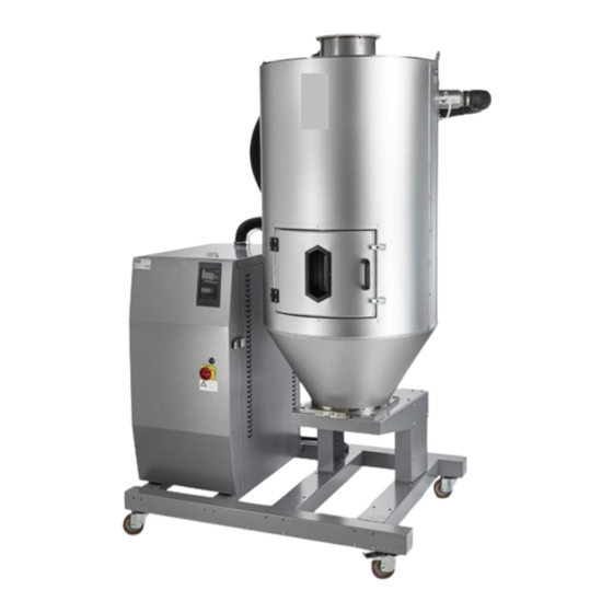
Chapter 2: Functional Description General Description The ADP series dehumidifying dryer is a machine to dehumidify plastic granules, so that they can be used in presses/extruders. Typical Features and Components The ADP dryer has optional material loading/unloading hopper and process chamber. The hopper unit contains the plastic granules to be dehumidified and can have different dimensions. - Page 12 Figure 2: Process chamber The process heater (1) provides a constant air temperature to the hopper, set by means of the HMI operator interface. A constant air temperature allows optimal processing of plastic material within the hopper. ADP 0250-2500 DRYER 882.99903.000 6/01/2023...
- Page 13 Figure 3: Dehumidifier unit Dehumidifier Unit 1 Regeneration filter Regeneration blower 2 Process filter Process Blower 3 Desiccant rotor Inverter (not shown) 4 Regeneration heater The rotor is the main core of the dehumidifier unit, which operates continuously and absorbs moist air from the hopper, regenerates it and supplies dry air to the hopper in a continuous cycle.
- Page 14 Residual risk due to hot surfaces in the moist air discharge area There is a residual risk for the operator and maintenance technician, due to possible burns where moist air is discharged into the environment (9). Ensure the regeneration exhaust cannot cause injury to people or damage to property.
-
Page 15: Operational Flow
Operational Flow The following is a diagram of the production process by means of a flow chart which highlights the various operating phases. 1. A rotor comprised of molecular sieve desiccant is in the machine, with high moisture absorption capacity. 2. - Page 16 Figure 5: Operational Flow Process Heater ADP 0250-2500 DRYER 882.99903.000 6/01/2023...
-
Page 17: Chapter 3: Installation
Chapter 3: Installation Uncrating the Equipment The machines that are shipped packaged on a truck or container must be unloaded with a forklift, overhead crane or crane using a harness and a "lifting beam" if necessary. In this case, ensure that taut ropes are well secured and there is no risk they may slip and consequently causing the crate to fall. -
Page 18: Storage & Remove & Open Shipment
Storage & Unpacking For the entire period the machine remains inactive before unpacking it, store it in a dry place at a temperature between + 41°F (5°C) and + 122°F (50°C) and in a position that is protected from the weather. For the entire period the machine remains inactive after being unpacked, waiting for commissioning or due to breaks in production, protect it with tarps to prevent accumulation of dust on the gears. -
Page 19: Initial Start-Up
Figure 7: Lifting bolts Initial Start-up Unless differently agreed upon the order, the machine is meant to work properly under the environmental conditions shown in the following items: POSITIONING THE PARTS OF THE MACHINE Place the parts as established by the plant and system layout; the manufacturer shall not be responsible for any problems encountered due to failure to do so. - Page 20 Figure 8: Placement of equipment 1000 mm (40”) Front View 1500 mm (60”) Top View 1500 1500 (60”) (60”) 1500 mm (60”) TEMPERATURE The machine can operate at room temperature between + 59°F (15°C) and + 104°F (40°C). LIGHTING The machine is fitted with built-in lighting appropriate for operations when a lack of this device may cause risks even if the ambient lighting is normal.
-
Page 21: Making Electrical Connections
Making Electrical Connections The machine’s electrical connection to the mains should be made by an authorized electrician personnel, in compliance with the current regulation for country of use. Check that the supplied voltage and frequency on the name plate of the machine match those of electrical instruments and check that the electrical circuit is properly sized for the maximum machine power supply (refer to the technical data of the table and the wiring diagram). -
Page 22: Chapter 4: Operation
Chapter 4: Operation Control and Signaling Systems The functions of the main control and signaling devices are given in the wiring diagram attached to this manual. REF. DESCRIPTION OPERATOR PANEL WITH TOUCHSCREEN This is the HMI control terminal where the messages and pages for the operator are displayed and has touch buttons to enter commands. -
Page 23: Electrical Cabinet
Electrical Cabinet The machine houses all the electrical instruments required to run the machine in automatic mode. Machine activation is handled by the control panel and electrical disconnection is guaranteed by the main switch (1). The main switch controls the main power supply of the entire machine: O = cuts off power supply to the machine (OFF) I = supplies power to the machine (ON) -
Page 24: Safety Devices
UL / CSA standards The machine has been manufactured with electrical devices and equipment compliant with electrical standards approved by the UL (Underwriters Laboratories Inc.) and/or CSA (Canadian Standard Association) standards: AWG-UL / CSA sleeves and wires. UL/CSA marked components for high voltage circuit. 24V low voltage circuit divided into branches that are individually protected by a 4A fuse, where components using this voltage are not UL/CSA marked. - Page 25 GUARD/SAFETY DEVICES- POSITION TYPE OF HAZARD SAFEGUARDED Fixed guard Cover to allow access to the external process heater Fixed guard Cover to allow access to the dehumidifier unit Mobile guard Hinged door with handle to allow access within the hopper The fixed guards are specified: The dimensions of the fixed guards are such that they do not leave openings in the protected dangerous working area when they are securely in place.
-
Page 26: Lockout-Tagout
Figure 11:Guard/Safety Devices Lockout-Tagout Lockout-tagout is a safety procedure used to ensure that the machine is adequately locked and cannot restart before you have completed the operation being carried out (e.g. routine maintenance). Before starting any operation, the dangerous supply sources need to be disconnected and made non-operational. -
Page 27: Starting Procedure
Operate as follows to lock the main switch before carrying out any operation on the machine: Set the main switch to OFF (0) and then lock it by inserting the padlock into the dedicated slot. Each operator must have a padlock with key available (only the operator that carries out the operation must hold the key to the padlock;... -
Page 28: Stopping Procedure
Stopping Procedure Controlled shutdown To stop the dehumidification process, proceed as follows: Operate on the O/I power button (2). Immediate stop STOP FOR POWER FAILURE A stop because of a power failure determines an immediate stop of the power supply to the machine actuators (uncontrolled stop). - Page 29 Product Loading/Unloading Feed product to be dried in the top of the hopper (1A). Unload the dried product by opening the gate (2A) at the bottom of the hopper. After loading the product into the dryer, it can be set up and adjusted. Check/set the required parameters for the dehumidification process by means of the HMI operator interface (3).
- Page 30 Exhibit 14: On / Off ADP 0250-2500 DRYER 882.99903.000 6/01/2023...
-
Page 31: Chapter 5: Maintenance
Chapter 5: Maintenance Maintenance Requirements Before proceeding with a task, the maintenance technician must assess whether the machine or line must be disconnected from power supply sources. It should be noted that the greater the care taken with adjustments and routine/scheduled maintenance the longer the machine will maintain good operating condition and the lesser the likelihood of it requiring major maintenance/repair. - Page 32 We recommend using compressed air to remove production residual dust. Clean the surfaces, levels and fixed units (i.e. those that do not receive a dedicated lubrication, such as guides and shoes) with a damp cloth then wipe with a dry non- abrasive cloth.
-
Page 33: Routine Maintenance
Routine Maintenance Periodic cleaning tasks RECOMMENDED FREQUENCY TASK UNIT TOOL (hours) Check and clean the process filter Dehumidifier Vacuum cleaner (1) if necessary. Check and clean the regeneration Dehumidifier Vacuum cleaner filter (2) if necessary. Check and clean the blower filter Dehumidifier Vacuum cleaner (3) if necessary. - Page 34 Periodic safety device checks FREQUENCY TASK INVOLVED PART METHOD (hours) Warning and Functional checking (replacement if Checking signalling devices malfunctioning). Functional checking (replacement if Checking Temperature probes malfunctioning). Checking the operation of the main Checking Main electric switch electric switch. Check the visual integrity of the Checking Electrical circuits...
- Page 35 Regeneration Filter cleaning Unscrew the locking device and remove the filter cover (2). Clean the cartridge with a jet of air from inside to the outside and check for damage. If the cartridge is broken or it cannot be cleaned, replace it with a new cartridge. Reassemble previously removed parts, paying attention to the sealing elements.
-
Page 36: Chapter 6: Troubleshooting
Chapter 6: Troubleshooting Introduction The utmost in safety precautions should be observed at all times when working on or around the machine and the electrical components. All normal trouble-shooting must be accomplished with the power off, circuit breakers turned off, and with the machine tagged as out of service. - Page 37 03 - ALARM ST Thermal protection of the Check the pipe connection process heating chamber. A between the dryer and the mechanical safety heating chamber; check the thermostat installed in the connection of T4 and T5. engaged heater body has Check the process blower tripped.
- Page 38 32 - WARNING DP-S Dew point lower than set Wait for an hour and check value. for the operation of the dehumidifier if the value has not increased. 36 - CLEAN SUCTION Vacuum filter. Clean the vacuum filter at FILTER the back of the dehumidifier.
-
Page 39: Chapter 7: Appendix
Chapter 7: Appendix Customer Satisfaction Warranty Program The terms and conditions of the warranty set forth are for one (1) year from the original date of purchase by the original purchaser. The manufacturer warrants to the original purchaser the product and/or goods to which this disclaimer is attached, and manufactured by us, to be free from defects in material and workmanship under normal use and service. -
Page 40: Technical Specifications
Technical Specifications Machine technical characteristics Voltage 480V, constant voltage: +/- 10% Frequency 60Hz, the tolerance is +/- 1% continuously; +/- 2% for brief periods. Harmonics The harmonics distortion is due to the sum of harmonics, from the second to the fifth, which does not exceed 10% of the total voltage value between active leads. -
Page 41: Drawings And Diagrams
Drawings and Diagrams Figure: 19 – ADP160-250 Machine Layout ADP 0250-2500 DRYER 882.99903.000 6/01/2023... - Page 42 Figure: 20 – ADP160-250 Electrical System ADP 0250-2500 DRYER 882.99903.000 6/01/2023...
- Page 43 ADP 0250-2500 DRYER 882.99903.000 6/01/2023...
- Page 44 ADP 0250-2500 DRYER 882.99903.000 6/01/2023...
- Page 45 ADP 0250-2500 DRYER 882.99903.000 6/01/2023...
-
Page 46: Spare Parts List
Spare Parts List Figure 21: Exploded view of heating chamber spare parts ADP 0250-2500 DRYER 882.99903.000 6/01/2023... - Page 47 Figure 22: Exploded view of spare parts for ADP160/250 ADP 0250-2500 DRYER 882.99903.000 6/01/2023...
- Page 48 Figure 23: Exploded view of spare parts for ADP160/250 (cont) ADP 0250-2500 DRYER 882.99903.000 6/01/2023...
- Page 49 Figure 24: Electrical information Description Code Regeneration heater Process chamber Safety thermostat R1 Safety thermostat R2 Regeneration blower Process blower Transport blower Optional Rotor inlet regeneration temperature probe Rotor outlet regeneration temperature probe First blower temperature Process temperature probe Safety probe temperature RC Blower filter S2 RC Blower filter S3 Optional...
-
Page 50: Technical Assistance
Technical Assistance PARTS SUPPORT ACS welcomes inquiries on all your parts needs and is dedicated to providing excellent customer service. The ACS Customer Service Group will provide your company with genuine OEM quality parts manufactured to engineering design specifications, which will maximize your equipment’s performance and efficiency.
Need help?
Do you have a question about the ADP Series and is the answer not in the manual?
Questions and answers