Table of Contents
Advertisement
Quick Links
Advertisement
Table of Contents

Related Manuals for SOLARMG SG-OST50-60T


Summary of Contents for SOLARMG SG-OST50-60T
- Page 1 REV.0 – Preliminary S.MG-MU:SG-OST50-60T User Manual...
-
Page 2: Table Of Contents
REV.0 – Preliminary S.MG-MU:SG-OST50-60T Contents Forward- Application Model ______________________________________________________________ 01 lntended Audience _____________________________________________________________ 01 Symbol Conventions ____________________________________________________________ 02 1 Safety Precautions 1.1 Personnel Safety ___________________________________________________________ 1.2 The PV lnverter Protection ___________________________________________________ 1.3 lnstallation Safety ___________________________________________________________ 1.4 Electrical Connections _______________________________________________________ 1.5 Operating and Commissioning ________________________________________________ 1.6 Maintenance _______________________________________________________________... - Page 3 REV.0 – Preliminary S.MG-MU:SG-OST50-60T 4.4.1 Determining the lnstallation Position ______________________________________ 13 4.4.2 lnstallation Mode Requirements __________________________________________ 16 4.5 Support-mounting the lnverter________________________________________________ 16 4.6 lnstallation Self-check _______________________________________________________ 17 5 Electrical Connections 5.1 Connecting Protection Ground (PGND) Cables __________________________________ 5.1.1 Preparation __________________________________________________________ 5.1.2...
- Page 4 REV.0 – Preliminary S.MG-MU:SG-OST50-60T 11 Technical Specifications 12 Technical Assistance...
-
Page 5: Forward
REV.0 – Preliminary S.MG-MU:SG-OST50-60T Introduction Dear User, This user manual introduces the inverter in terms of its installation, electrical connections, operation, commissioning, maintenance, and troubleshooting. Please read through the manual carefully before installing and using the inverter, and keep the manual well for future reference. -
Page 6: Symbol Conventions
REV.0 – Preliminary S.MG-MU:SG-OST50-60T Symbol Conventions Safety symbols used in this manual, which highlight potential safety risks and important safety information, are listed as follows: Symbol Description lndicates an imminently hazardous situation which, if not correctly DANGER followed, will result in serious injury or death. -
Page 7: Safety Precautions
REV.0 – Preliminary S.MG-MU:SG-OST50-60T 1 Safety Precautions Please read these safety precautions in User Manual carefully. 1.1 Personnel Safety a. The PV inverter must be installed, electronically connected, operated and maintained through specially trained technician; b. The qualified technician must be familiar with the safety regulations of electrical system,... -
Page 8: Electrical Connections
REV.0 – Preliminary S.MG-MU:SG-OST50-60T 1.4 Electrical Connections Before installing the inverter, check all electrical ports to ensure no DANGER damage and no short circuit. Otherwise personal casualty and/or fire will occur. a. Input terminals of the PV inverter apply only to input terminals of PV String; do not connect any other DC source to the input terminals. -
Page 9: Additional Lnformation
REV.0 – Preliminary S.MG-MU:SG-OST50-60T a. For personal safety, maintenance personnel must wear appropriate personal protective equipment (like insulation gloves and protective shoes) for the inverter maintenance. b. Place temporary warning signs or erect fences to prevent unauthorized access to the maintenance site. -
Page 10: Overview Of The Lnverter
REV.0 – Preliminary S.MG-MU:SG-OST50-60T 2 Overview of the lnverter This chapter introduces the inverter and describes its functional model, network application, appearance, dimensions, and working process etc. 2.1 Functional Models 2.1.1 Function This series is a three-phase grid-tied PV string inverter (transformer less) that converts the DC power generated by PV strings into AC power and feeds the power into power grid. -
Page 11: Outline And Dimensions
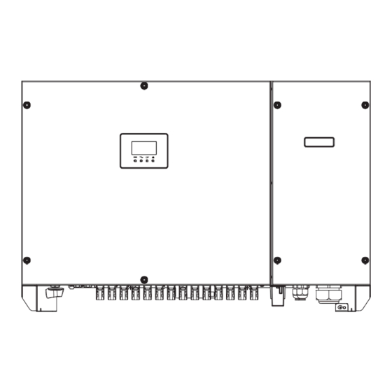
REV.0 – Preliminary S.MG-MU:SG-OST50-60T Figure 2.2 a low-voltage grid-tied power system Figure Power grids supported by these series inverters 2.3 Outline and Dimensions 2.3.1 Outline Figures 2.4 to 2.6 show the outline of the inverters as follows: Figure front view and amplification effect of... -
Page 12: Dimensions
REV.0 – Preliminary S.MG-MU:SG-OST50-60T Figure rear view of this series inverter Figure The bottom view of this series inverter 2.3.2 Dimensions Figures 2.7 shows the dimensions of these series inverters as follows: Figures dimensions of this series (unit:... -
Page 13: Working Modes
REV.0 – Preliminary S.MG-MU:SG-OST50-60T 2.4 Working Modes Three working modes of the inverter are shown as follows: standby, operating, and shutdown. Table 2.1 shows the conditions for the inverter lo switch between working modes. Modes Description The PV inverter enters the standby mode when >the... -
Page 14: Storage -10
REV.0 – Preliminary S.MG-MU:SG-OST50-60T 3 Storage This chapter describes the storage requirements for the inverter. The following storage instructions apply if the PV inverter will not be deployed immediately: Do not unpack the inverter (put desiccant in the original box if the PV inverter is unpacked). -
Page 15: Checking The Outer Packing
REV.0 – Preliminary S.MG-MU:SG-OST50-60T 4 lnstallation Do not install the inverter on flammable building materials or in an DANGER area that stores flammable or explosive materials. Do not install the inverter in a place where personnel are likely to CAUTION... -
Page 16: Moving The 50K/ 60K
REV.0 – Preliminary S.MG-MU:SG-OST50-60T lf any damage mentioned above is found, contact the dealer NOTICE immediately. 4.2 Moving the SOK / 60K After checking the outer packing, move the PV inverter to the designated installation position horizontally. Hold the handles on both sides of the inverter, as shown in Figure 4.2. -
Page 17: Compliance And Safety Symbols
REV.0 – Preliminary S.MG-MU:SG-OST50-60T 4.3.2 Compliance and Safety Symbols Safety symbol Description Electrical shock! There are residual voltages in the PV inverter. It needs 10 minutes lo finish discharge. The PV inverter must not be touched when in operation. enclosure and heat sinks are extremely hot. - Page 18 REV.0 – Preliminary S.MG-MU:SG-OST50-60T The inverter must be installed in a well ventilated environment to ensure good heat dissipation. The inverter must be free from direct exposure to sunlight, rain, and snow to extend its service life. lt is recommended that the inverter be installed in a sheltered place. lf no shelter is...
- Page 19 REV.0 – Preliminary S.MG-MU:SG-OST50-60T Figure lnstallation Space Requirements (unit: When installing multiple inverters, install them along the same line (as shown in Figure 4.5) if sufficient space is available, and install them in triangle mode or in stacked mode (as shown in Figure 4.6) if no sufficient space is available. The installation modes ensure...
-
Page 20: Lnstallation Mode Requirements
REV.0 – Preliminary S.MG-MU:SG-OST50-60T 4.4.2 lnstallation Mode Requirements lnstall the inverter upright or at a maximum back tilt of 15 degrees to facilitate heat dissipation. Below are some correct wrong installation modes, as shown in Figures 4.7&4.8. Figures 4.7 The... -
Page 21: Lnstallation Self-Check
REV.0 – Preliminary S.MG-MU:SG-OST50-60T Step 2 Tighten the rear panel with the support using M12 bolt to a torque of 42 N.m (as shown in Figure 4.10). Figure 4.10 Tightening the rear panel with the support Step 3 Mount the inverter on the support and tighten the inverter with rear panel using screws, as shown in Figure 4.11. -
Page 22: Electrical Connections -18
REV.0 – Preliminary S.MG-MU:SG-OST50-60T 5 Electrical Connections Before performing any electrical connections, ensure that both DC and AC Switches are OFF. Otherwise, fatal injury can occur due to DANGER the high voltage caused from AC and DC cables. Grounding the PV Strings needs below prerequisites: CAUTION An isolation transformer must be installed on the AC side of each inverter;... -
Page 23: Wiring Procedures
REV.0 – Preliminary S.MG-MU:SG-OST50-60T It is recommended that the ground cable be connected to a nearby ground position. For a system with multiple inverters connected in NOTE parallel, connect the ground points of all inverters lo ensure equipotential connections. 5.1.2 Wiring Procedures Step 1 Remove an appropriate length of the insulation layer from the PGND cable using a wire Stripper;... -
Page 24: Connecting Ac Output Cables
REV.0 – Preliminary S.MG-MU:SG-OST50-60T 5.2 Connecting AC Output Cables 5.2.1 Preparation The AC power cable and AC terminals have been prepared with below requirements. a. AC power cable: Outdoor multi copper-cores cables are recommended. Table 5.1 describes specifications. Cross-sectional Recommended... -
Page 25: Procedure Of Connecting Ac Cables
REV.0 – Preliminary S.MG-MU:SG-OST50-60T 5.2.2 Procedure of Connecting AC Cables AC wiring chamber in on the right side of the inverter, and before AC wiring, remove these four retaining screws, uninstall Earth wire, and remove the cover of AC wiring chamber. Please follow below steps to ensure equipment and personal safety. -
Page 26: Connecting The Pv Strings
REV.0 – Preliminary S.MG-MU:SG-OST50-60T For operation convince and safety, the inverter requires multi-stranded wire and crimping terminals with a proper crimping tool before wiring. NOTICE avoid potential risk, 125A 400VAC overcurrent protection device is recommend to add on the output terminal. -
Page 27: Preparation
REV.0 – Preliminary S.MG-MU:SG-OST50-60T 5.3.1 Preparation PV Strings DC input cable and connectors have been prepared; refer to No. of DC input terminals at the bottom of inverter shown in below figure: 50K with 10 routes and 60K with 12 routes, if quantity of PV strings is less than number of input on inverter, you can refer to below Table for the installation of PV strings and the inverter. - Page 28 REV.0 – Preliminary S.MG-MU:SG-OST50-60T Connectors of PV Strings: Positive and negative DC input connectors are used, as shown in Figure 5.6 and Figure 5.7. Figure Positive connector compositions Figure Negative connector compositions Positive and negative metal connectors are packed with positive and negative connectors respectively when shipped out.
- Page 29 REV.0 – Preliminary S.MG-MU:SG-OST50-60T Step 2 lnsert the exposed areas of the positive and negative power cables into the metal terminals of the positive and negative connectors respectively and crimp them using a crimping tool, as shown in Figure 5.9.
-
Page 30: Connecting Communications Cables
REV.0 – Preliminary S.MG-MU:SG-OST50-60T Figure 5.12 Checking voltage of every route Strings lnsert the positive and negative connectors into their corresponding terminals of the Step 6 inverter until a "click" sound is heard, as shown in Figure 5.13. Figure 5.13 Connecting... - Page 31 For more details, refer to RS485 switching Product Application Manual. You can choose and buy WIFI GPRS RS485 communication modules from SolarMG. NOTE WIFI GPRS are available from SolarMG RS485 Table 5.3 WIFI & GPRS & Modules Description Only permitting to connect inverter's communication interface with...
-
Page 32: Connecting Rs485 Communications Cables
REV.0 – Preliminary S.MG-MU:SG-OST50-60T Figure 5.15 RS485 communications multiple inverters lf multiple inverters are connected, note the following: 1) No need for re-setting Modbus address and the address can be allocated automatically if V1000 data logger is used. Otherwise, you need to re-set Modbus address manually through SolarTouch APP if other brand data logger is used. - Page 33 REV.0 – Preliminary S.MG-MU:SG-OST50-60T Step 1 Remove the wiring chamber on the right of inverter, and loosen the locking cap on 485 waterproof cable connector from the bottom of inverter. Step 2 Remove an appropriate length of the insulation layer from the communications...
-
Page 34: Setting Rs485 Communications Address
REV.0 – Preliminary S.MG-MU:SG-OST50-60T 5.4.3 Setting RS485 Communications Address SolarTouch Step 1 scanning below QR code. And then login App and register an account for your inverter. Figure 5.17 Code for downloading SolarTouch Step 2 Click “Bluetooth connection”, Then scan the machine SN bar code in the label or press “Manual connection”... - Page 35 REV.0 – Preliminary S.MG-MU:SG-OST50-60T address in Figure 5.19, the default address is 1, click to modify the address and save it, the inverter at same RS485 bus must be set a unique address. Figure 5.19 Check Modbus address...
- Page 36 REV.0 – Preliminary S.MG-MU:SG-OST50-60T Step 4 Press “Console”à “Feature Parameters”à “Terminal Resistor”. You can set Terminal Resistor of the end of multi-RS485 connection chain, as showed in Figure 5.20. Figure 5.20 Setting Terminal resistor 5.5 lnstallation Verification Check the following items after the inverter is installed according to Table 5.4.
-
Page 37: System Operation
REV.0 – Preliminary S.MG-MU:SG-OST50-60T 6 System Operation 6.1 Powering ON the lnverter Switch ON the AC circuit breaker. Step 1: Set the DC SWITCH of the inverter to ON. Step 2: Observe statuses of LED indicator lights on the inverter according to Table 7.2. -
Page 38: User Lnterface -33
REV.0 – Preliminary S.MG-MU:SG-OST50-60T 7 User lnterface Display screen of inverter is composed of LED indicator and LCD (LCD is optional for some models of inverter). LED indicator includes PV lndicator, Grid lndicator, COM lndicator, and Warning lndicator. LED indicator Status... - Page 39 REV.0 – Preliminary S.MG-MU:SG-OST50-60T LCD Screen Warning 1) COM When WIFI/GPRS/Bluetooth is transferring data, icon will be while no data transmission, the icon will be off after 10s. When RS485 is transferring data, icon will be while no data transmission, the icon will be off after 10s.
- Page 40 REV.0 – Preliminary S.MG-MU:SG-OST50-60T 5) Meter Normal status: today and total energy, MPPT voltage and current are showed in turn. Standby status: counter down value before inverter start up. status: setting parameters via APP, the screen keep for 5 seconds.
- Page 41 REV.0 – Preliminary S.MG-MU:SG-OST50-60T Grid absent Grid over frequency © © Grid under frequency Grid unbalance PV over voltage PV under voltage © © Weak radiation Strings abnormal lnverter over temperature © © © Fan abnormal • lnsulation resistance abnormal •...
- Page 42 REV.0 – Preliminary S.MG-MU:SG-OST50-60T Table LED indicator status far common fault of the inverter...
-
Page 43: Maintenance
REV.0 – Preliminary S.MG-MU:SG-OST50-60T 8 Maintenance Before maintaining and commissioning inverter and its peripheral distribution unit, switch off all the charged terminals of the inverter WARNING and wait at least 1O minutes after the inverter is powered off. 8.1 Routine Maintenance... -
Page 44: The Lnverter Troubleshooting
REV.0 – Preliminary S.MG-MU:SG-OST50-60T 8.2 The lnverter Troubleshooting When inverter enters in shutdown mode abnormally, the alarm light is illuminated. Table 8.2 describes the troubleshooting measures for common fault alarms in the inverter. Alarm Name Causes Measures Recommended Grid 1. lf the alarm occurs accidentally, possibly the power grid is abnormal accidentally. - Page 45 REV.0 – Preliminary S.MG-MU:SG-OST50-60T The insulation resistance against 1. lf the alarm occurs accidentally, possibly the external the ground at the input side circuits are abnormal accidentally. The inverter Residual decreases automatically recovers to the normal operating status Current during the inverter after the fault is rectified.
-
Page 46: Removing The Lnverter
REV.0 – Preliminary S.MG-MU:SG-OST50-60T remote monitor lf modem or other data logger is used, please reboot Communications displays zero it; if still does not work after rebooting, contact your outage power generation dealer. remote monitor Output switch Check if DC switch is damaged, and if not, switch it to... - Page 47 REV.0 – Preliminary S.MG-MU:SG-OST50-60T Step Remove the inverter from the rear panel. Step Remove the rear panel. Before removing DC input connector, double check DC input switch WARNING is turned to OFF to avoid inverter damage and personal injury. Outer fan is added to cool the inverter, check periodically and ensure that air inlet and outlet of fan is free from dust and blockage;...
-
Page 48: Quality Guarantee
REV.0 – Preliminary S.MG-MU:SG-OST50-60T 9 Quality Guarantee 9.1 Quality Terms 1) Where otherwise agreed to in a contract, quality warranty period of the inverter is 60 months 2) As for the PV inverter which is defective or damaged within its quality... -
Page 49: Disposal Of The Lnverter
REV.0 – Preliminary S.MG-MU:SG-OST50-60T 10 Disposal of the lnverter The PV inverter and its packing case are made from environmental protection material. lf the inverter service life has expired, do NOT cut it away with household garbage; dispose the inverter in accordance with local rules for disposal of electrical equipment... - Page 50 REV.0 – Preliminary S.MG-MU:SG-OST50-60T 11 Technical Specifications lnverter Model Input Max. input power 60,000W 70,000W Rated input power 52000W 62000W Max. input voltage 1100V Max. input current 39A/39A/26A/26A 39A/39A/39A/39A Max. short circuit current 45A/45A/30A/30A 45A/45A/45A/45A Max. feedback current Rated input voltage...
- Page 51 REV.0 – Preliminary S.MG-MU:SG-OST50-60T Power factor >0.99 Rated power >0.99 Rated power (Adjustable 0.8 lead- (Adjustable 0.8 lead- 0.8 lag) 0.8 lag) Overvoltage grade in accordance with IEC 62109-1 Protection Input DC switch, Input overcurrent & overload protections, Input reverse-connection protection, PV string fault detection, lnsulation resistance detection, low voltage ride-through, Output over current &...
- Page 52 REV.0 – Preliminary S.MG-MU:SG-OST50-60T lnstallation mode Support-mounting Input connector Amphenol H4 Output connector Water-proof connector+OT terminal Standards Compliance Grid standard /T32004 IEC62109-1, IEC62109-2,NB T32004 Safety certification Grid power voltage range can be set according to national voltage standards; Power grid frequency range can be set according to national grid standards The preceding technical specifications are subject to change without prior notice.
- Page 53 REV.0 – Preliminary S.MG-MU:SG-OST50-60T 12 Technical Assistance SolarMG offers a technical assistance and consultancy service. To take advantage of this service, the following number is active: 055911077.
Need help?
Do you have a question about the SG-OST50-60T and is the answer not in the manual?
Questions and answers